


My application for the DRV8301 integrated DC/DC requires a 5V output and operation from a large input voltage range (20-48V). Ideally, the DC/DC would be stable throughout the entire input voltage range. However at 48V, the design is right at the edge of pulse skipping. With typical load I have a perfectly stable output PWM. However, with just a small reduction in load I get periodic pulse skipping:
- Red : Inductor Current
- Yellow : PH node voltage
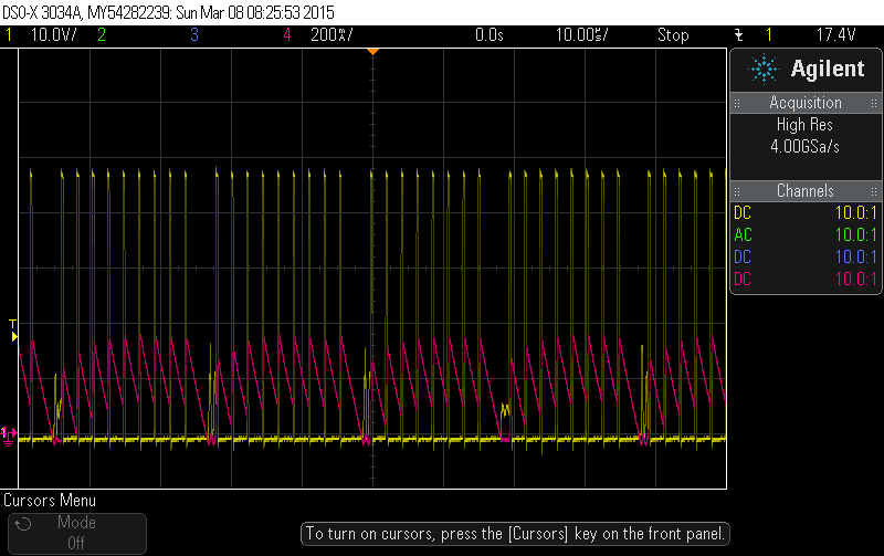
The pulse skipping is not caused by the minimum on time requirement (t_ON > 130ns). For 48V to 5V the max frequency is ~= 800kHz. I'm running at 450khz, and the on pulse-width is about 300ns. It looks like the converter is entering "Pulse Skip Eco-mode".
According to the datasheet:
The TPS54160A enters the pulse skip mode when the voltage on the COMP pin is the minimum clamp value.
The TPS54160A operates in a pulse skip mode at light load currents to improve efficiency. The peak switch
current during the pulse skip mode will be the greater value of 50mA or the peak inductor current that is a
function of the minimum on time, input voltage, output voltage and inductance value.
Unfortunately the datasheet doesn't do describe Eco Mode much more than this. Figure 8.2 (Function Block Diagram) seems to indicate that EcoMode is entered when COMP pin voltage is less than some threshold, however it doesn't specify what the threshold is or when in the switching cycles this matters. I've put a capture of the COMP pin voltage below.
- Red : Inductor Current
- Blue: COMP pin voltage
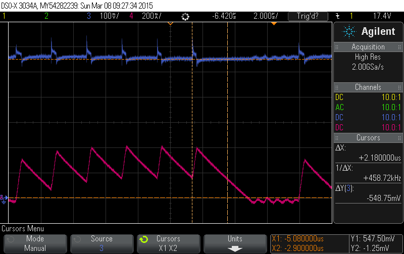
As you see the the threshold voltage seems to be about 500mV, and my design is just at the edge of pulse skipping mode.
I've tried variety of different thinks to keep the DC/DC from entering the pulse skipping mode. And a found a few things that seem to work:
- Adding small about of capacitance (100pF) from comp to ground. (My design uses ceramic output capacitors so it phase and gain margins are good with just RC compensation)
- Reducing PWM frequency.
- Increasing load current a bit.
- Reducing inductance.
ECO mode increases output voltage ripple a lot, so I would like to avoid it during normal operating conditions. I have two questions:
- Are other methods to change design in order to avoid ECO mode, or a way to disable ECO mode completely?
- Is there a formula I can use to determine COMP pin voltage when coming up with a design?
