This thread has been locked.

If you have a related question, please click the "Ask a related question" button in the top right corner. The newly created question will be automatically linked to this question.

Li-ion battery charger with power path management and 5V output

Other Parts Discussed in Thread: BQ24295, BQ24195

Hi All,

We are looking for a li-ion battery charger with power path management that satisfies the following use case scenario.

We have a requirement in which we need to design a standalone battery operated device that can also act as a power bank to a phone.

The following block diagram explains our use case.

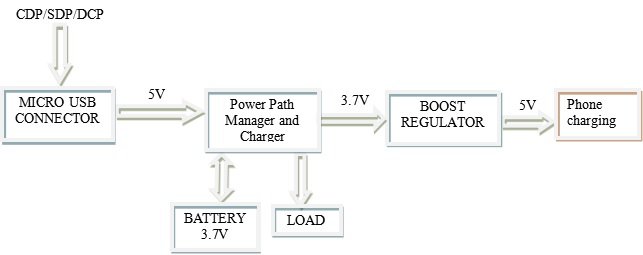
Lets assume the USB charging port is DCP(1.5A current) and the phone and battery charger detects it as DCP(Please assume the charging port detection mechanism by phone and charger is taken care of). In this case, the phone will try to draw 1.5A of charging current while there is an efficiency loss due to buck (inside charger) and boost regulator which will limit the current to way less than 1.5A.

 Is there any way we can get rid of buck and boost regulator so that the phone can charge at 1.5A? Is there any battery charger that can provide 5V output(same as USB input), while still monitoring its current for power path management?

Please suggest.

Thanks,

Naveen

  • Hello Naveen,
    For the diagram you have shown above, the bq2407x series of devices will work as the charger/power path manager. This is a simple linear charger with power path and allows 1A range of charge currents.

    We also have switch-mode chargers which incorporate power path and can generate external +5V from the battery rail if desired without a separate boost converter. Please review bq24195 and bq24295 devices for the power levels you are interested in.
  • Hello Upal,

    Thanks for the quick reply and suggestion.

    We need a clarification regarding BQ24195 for a use case which we are planning to implement.

    Use case:

    1. VBUS is connected to DCP source

    2. Phone is connected for charging on PMID pin(Phone expects 1.5A for charging as it also detects the source as DCP)

    3. Vsys is sourcing system load

    4. Battery is connected and say 50% charged.

    When VBUS is connected to a DCP source, PMID will be sourced by VBUS through Q1.

    For this use case, if the phone draws 1.5A for charging, will the power path manager take this into account and limit the current drawn by VSYS and Battery?

    Thanks,
    Naveen

  • Hi Upal,

    Eagerly waiting for suggestion.

    Thanks,

    Naveen

  • Hi Naveen,

    Please see the block diagram in section 8.2 of the bq24195 data sheet.

    www.ti.com/.../bq24195.pdf

    In this, it shows that the current sense (loop shown at top left of the diagram) senses the current from the VBUS pin, and the voltage at the VBUS pin as part of the input current and voltage DPM (dynamic power management) function. Thus all current flowing through Q1 and out the PMID node to the external phone will be counted as part of the total input current limit.

    I'll forward this request to the team that supports bq24195 directly in case they have additional feedback.

    thanks
  • The bq24295 is another option.
  • Hi Upal,

    Thanks for your detailed answer.

    In our use case, we have two loads (Phone and system load) when VBUS is connected. We would like to know which will get the first priority, whether PMID or VSYS?

    Thanks,

    Naveen

  • VBUS and PMID are separated by a FET. With power applied to VBUS, any load on PMID will reduce the current available to the buck converter for the system load at SYS and to charge the battery. When no power is applied to VBUS, the IC runs in boost mode and provides a 5V rail at PMID that is powered from the battery.
  • Hi Jeff,

    Thanks for your answer.

    We found that BQ24195 pretty much suits our requirement except for the charge termination current.

    The battery we are planning to use is 1700 mAh Li-ion battery. The minimum charge termination current supported by the BQ24195 is 128mA whereas the battery charge cut-off current is 0.01C which is 17 mA in our case. This looks to be a considerable difference and the battery will prematurely stop charging.

    Please suggest.

    Thanks,

    Naveen

  • Unfortunately, there is no method to lower the termination current value.  I suggest disabling termination.  The IC will continue to trickle charge the battery but not charge above the VBATREG setting.

  • Hi Jeff,

    Is there any precautions that we will have to take by disabling termination regulation? Are there any adverse effect in disabling the same?

    Thanks,
    Naveen