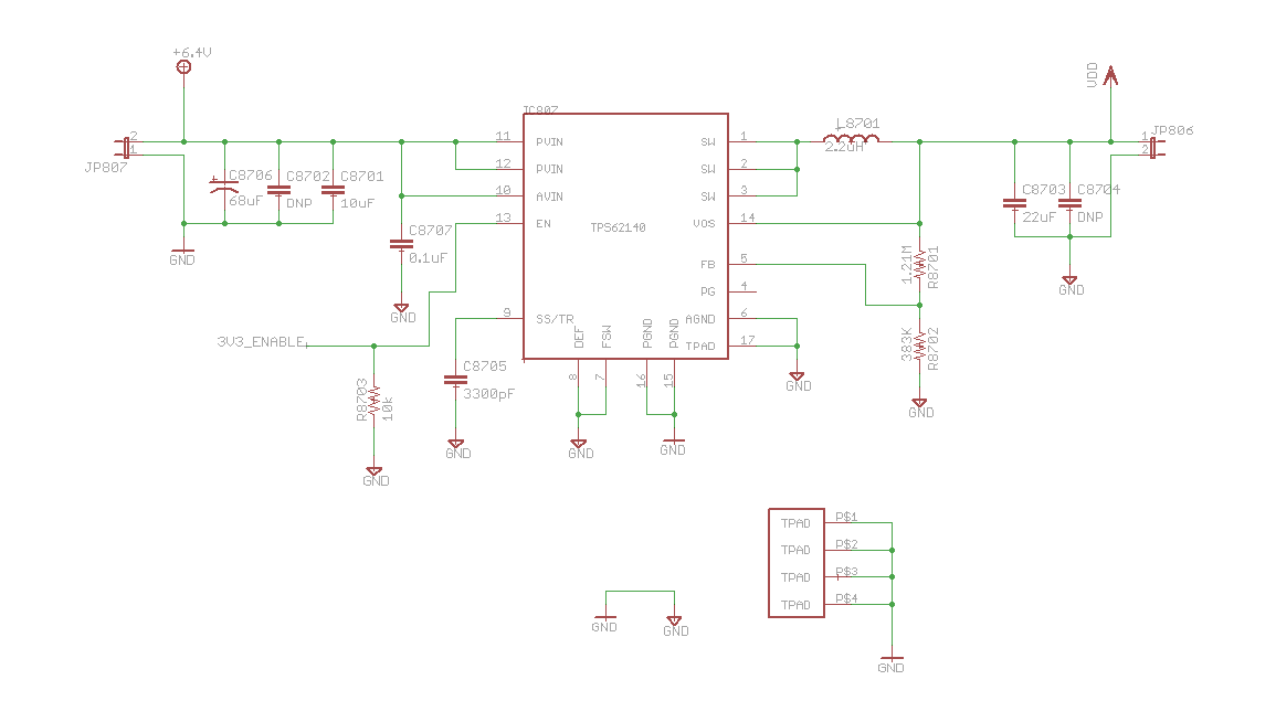
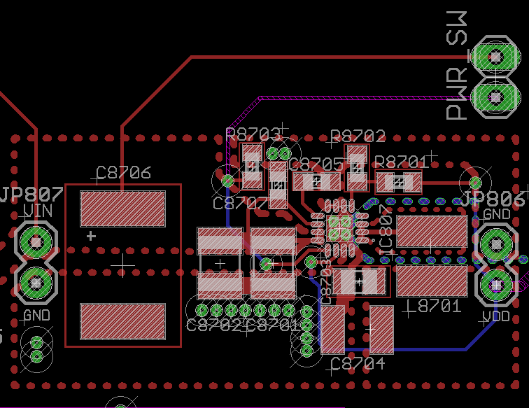
Our team is using two TPS62140s as main power regulators on our board to step down the voltage from a higher voltage to 3.3 and 5V. We followed TPS62140EVM-505's PCB layout and the same parts for our boards (just changing some resistor values according to the datasheet to get the desired output voltage). The only major difference is that we have a switch that en/disable the EN pin. We've experienced some issues.
Issue 1: we used both batteries and external power adapter as inputs. For batteries, @6.4V, never had issues; regulators output 3.3V and 5V consistently. However, when we used external power adapters (tried t two, one rated @12V, 6A and the other @6V, 1A), the regulator stopped working completely after power was applied. It was later on found the moment the power is applied, there was sometimes a negative spike from the power adapters. We thought this might be an problem (since abs. maximum rating of the IC's input voltage is -0.3V to 20V) so we put a relatively large cap (3000uF, 25V) on the input pins to avoid this from happening.
Issue 2: With the cap installed on the input, after using our switch to apply power a few times (worked fine), the regulator seems broke. Even with our switch open (EN pin should be low), after applying power, the IC still outputs 3.3V and 5V; it seems like the EN pin is stuck to HIGH. Please let me know if you guys have some insights on these issues.
Thanks!


