This thread has been locked.

If you have a related question, please click the "Ask a related question" button in the top right corner. The newly created question will be automatically linked to this question.

Intermittent loss of PowerGood on UCD9222 on C6657 evm

Other Parts Discussed in Thread: UCD9222, TMS320C6657

Hello,

I have a C6657 evm which is misbehaving, a random time after power up (minutes to tens of minutes) the board enters an unresponsive reset state. I have tracked this down to a power supply problem: the condition is forced by an FPGA if any of the multitude of DC/DC converters on the board drop their Power good signal for longer than 0.67us (32 48MHz clocks). I have gone through all the supplies on the board and the culprit seems to be the UCD9222 that that controls two core supplies. The supplies are nominally 1V, with one being fine controlled by the DSPs VCNTL pins; this I measure as 1.1V at power on.

So, my question is, what can cause the UCD9222 to drop its PowerGood output? Is it likely that the UCD9222 device is faulty? Or could there be some other problem on the board that is causing this behaviour? Is there anything else I can check to further debug this problem?

Thanks for you help.

John Wilkes

  • Hi John,

    What is the Power Good Off level of UCD9222 (you can see it from Fusion GUI)? Can you capture output voltage waveform when the Power Good signal is deasserted? 

    The Power Good signal will deassert when Vout is below Power Good Off level, and assert when Vout is above Power Good On level. 

    Thanks,

    Zhiyuan

  • Hi Zhiyuan,

    Thank you very much for your rapid response. Unfortunately I do not have the Fusion GUI software or (more importantly) the USB interface hardware required to use it. However, the EVM I am using is a standard product, is there a way to find out how the UCD9222 is programmed for this board?

    I have done some more investigation: The device provides two supplies, the first is the nominal 1V supply that is tweaked by the DSP (CVDD) and the second is a fixed 1V supply (VCC1V0). First looking at the three power good outputs: PowerGood goes low first, followed by PG2 2.5us later. PG1 stays high for (as far as I can tell) many milliseconds after this. This is itself a little odd since PowerGood appears to precede PG2 though the data sheet suggests that PowerGood is the logical AND of PG1 and PG2.

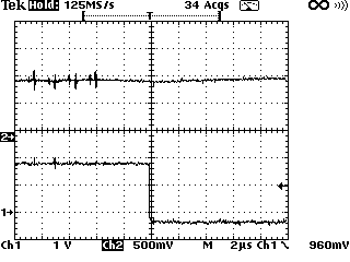
    Next I look at the output voltage rails themselves as you suggested. CVDD (output 1) appears fine though there is often a few spikes of noise a few microseconds before the power off event. These spikes dip to 0.86V and peak at 1.22V though I cannot be sure they are actually present on the rail - I suspect this noise is being inductively picked up by my scope probe. Here is a screen shot of my scope, the lower trace is the PowerGood output, the top trace is the CVDD rail.

    VCC1V0 (output 2) is more interesting. This rises sharply about 20us before the power off event. Gets to over 2V and then starts dropping again. Here is the scope grab, this time the top trace is the VCC1V0 rail, note the different time base on this one:

    So, although the rail isn't going low, it is definitely going too high - will this also cause PowerGood to drop? What could cause this spurious rise in voltage? Could this damage the processor?

    Thanks again for your help.

    John.

  • Hi John,

    The PG signal is asserted when Vout is above PG_ON threshold. Based on the FW version I have, for the 1.0V rail, PG_ON is 0.9V; for the 1.1V rail, PG_ON is 0.917V. 

    The PG signal is de-asserted when Vout is below PG_OFF threshold. Based on the FW version I have, for the 1.0V rail, PG_OFF is 0.85V; for the 1.1V rail, PG_OFF is 0.857V.

    Also, PG signal is de-asserted when the PWM is shut down, which can be triggered by OV fault and Fast OC fault.

    In your 1.1V rail snapshot, I think the PG signal is de-asserted because Vout is below PG_OFF threshold. The PWM operation will continue, though.

    In your 1.0V rail snapshot, I believe the 2V overshoot triggered OV protection which shuts down the PWM, and as a result, the PG signal is de-asserted.

    The time lag between PG2 and PowerGood is because FW needs time to execute. The logic AND is not done by HW AND gate.

    The rise in voltage is probably caused by load transient. But normally the overshoot is controlled within a small range (tens of mV). So something is wrong on the board, possibly related to UCD9222's power stage. The 2V voltage may damage the processor. You'll need to check the processor's datasheet.

    Best regards,

    Zhiyuan 

  • The documentation for the DSP EVM can be found from TI's webpage for the EVM (http://www.ti.com/tool/tmdsevm6657?keyMatch=c6657&tisearch=Search-EN-Everything). Scroll down to Technical Documents, then Third Party Documents (TI outsources the design of the DSP EVMs) and click on the Technical Documentation & Schematics for TMS320C6657 ....  This will take you to the eInfochips landing page containing the board documentation which includes the project file for the UCD9222.

    It doesn't appear that AVS (Adaptive Voltage Scaling) is used on the C6657 as both rails have been set to ignore the VID inputs so they should remain at a fixed level defined by Vout Command.  Unless they are using Vout Command to alter the voltage setpoint but I am not aware that they have implemented this method.

    The likely reason for the PowerGood falling is the OV Fault limit tripping for Rail #2, it is set to shutdown immediately.

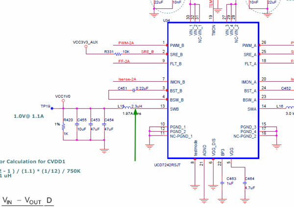
    Can you provide a scope shot of the SW node for Rail#2, this would be the driver side of L15 as shown below, during the time when the voltage is rising and during normal operation?  It will need to have enough detail to determine the pulse width of the PWM signal (4-6 pulses)

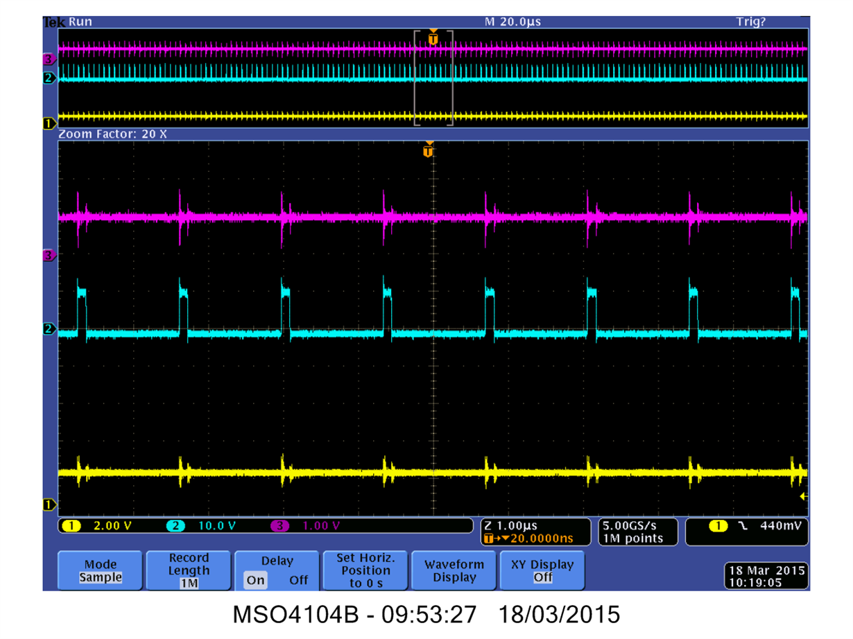
  • Thank you Zhiyuan and Brad for your continued help with this matter. I have commandeered a better oscilloscope and taken the data you requested. First the SWB pin in normal operation, after power up but before the power down event occurs. The yellow (bottom) trace is PowerGood, the magenta (top) trace is the VCC1V0 rail and the cyan (middle) trace is SWB pin. Note that my scope probe is acting like a nice antenna: the simple act of connecting it to the SWB pin puts spikes of noise on the other traces coincident with the PWM edges. This does not seem to bother the operation of the circuit though:

    Next is the same set up during the power down event triggered by a falling edge of the PowerGood signal:

    Does this offer any further clues?

    Thanks again.

    John.

  • Hi John,

    You may try adding some dummy load in parallel with the output capacitor, say a 40 ohm 0805 resistor, and see if it mitigates the problem.

    Thanks,

    Zhiyuan
  • Hi Zhiyuan,

    Thanks for your continued help. Just to let you know: I installed a 39 ohm 0805 resistor in parallel with C454 and it has not solved the problem, the board continues to intermittently reset.

    Cheers,

    John.

  • Hi John,

    We would like to take your malfunctioned C6657EVM and send to you a new one. If it works for you, please leave your email and we can contact offline.

    Thanks,

    Zhiyuan

  • Hi Zhiyuan,

    Thank you, that is a really kind offer. My email address is john.wilkes@renishaw.com.

    Thanks again.

    John.