This thread has been locked.

If you have a related question, please click the "Ask a related question" button in the top right corner. The newly created question will be automatically linked to this question.

TPS2115 switching issue

Other Parts Discussed in Thread: TPS2115, TPS62140

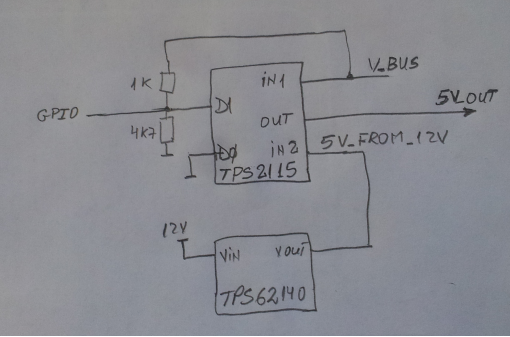
We use a TPS2115 to switch between two 5V supplies. One is usb V_BUS and another one is an 5V output generated from a 12V input using a TPS62140 (see attached drawing). When we disconnect V_BUS than the voltage on TPS2115 pin IN1 and OUT are as shown in the attached files.

What could be the issue?

Thanks,

Valentin

  • Hello Valentin,
    could you please send us the load current waveform as well.
    what is the load capacitance used in this design. may be try increasing the output cap.

    Regards
    Dinesh
  • Hi Dinesh,

    Unfortunately we will not be able to measure current waveform as I am not able to insert a resistor on the ground between the TPS2115 and the load.

    The load capacitance is as follows: on V_BUS is 10uF, on 5V_OUT is 860uF, on 5V_FROM_12V is 22uF.

    Which capacitance do you suggest to increase?

    Regards,

    Valentin

  • Anybody else here that could help with this issue?
  • hi Valentin,

     I was suggesting to increase the 5V_OUT capacitor , but looks like you have enough.

    is there any chance that input itself is dripping while you feed the power to the load?

    that is why I wanted the input and out put voltage and current waveform.  it will be difficult  to  analysis without these waveform. 

     are you using  our EVM or you built the design on your own PCB. Please  make sure that your schematic is correct.

    Regards

    Dinesh


  • Hi Dinesh,

    We use the design in our own PCB - we checked the pinout one more time and they are correct.

    We discovered the issue was the GPIO was toggled from the microcontroller and was causing the switch to an input that didn't have voltage on it which in reverse was causing the microcontroller to reboot.

    What we try to design is:

    a) The switch is in manual mode with D0 being 0 all the time

    b) If there is voltage on IN1 we want the output connected to IN1 all the time (no matter IN1>IN2 or the other way around)

    c) If there is no voltage on IN1 the switch should connect the output to IN2

    d) We should be able to manually switch, using GPIO, to either IN1 or IN2 (when both of them have voltages on them).

    We achieved a), b) and c) with our design but the microcontroller is not able to drive low the D1 line.

    We use a level translator between the microcontroller and the switch D1 pin.

    Do you have any suggestion for achieving d) item ?

    Valentin

  • Hello Valentin,
    I suggest you go thru the EVm user guide of TPS2115 at the below link.... plesae study sections- 2.3, 2.3.2 and 2.4

    www.ti.com/.../sllu054.pdf.
    I hope this will solve your problem.

    Regards
    Dinesh