This thread has been locked.

If you have a related question, please click the "Ask a related question" button in the top right corner. The newly created question will be automatically linked to this question.

bq24195/ Hostless operation

Other Parts Discussed in Thread: BQ24195, BQ24295, BQ25895

Hello,

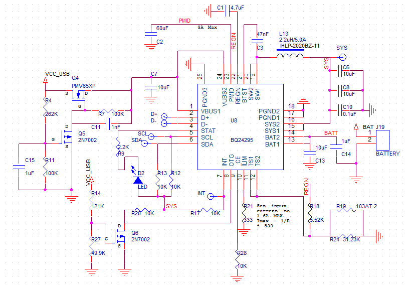
I am considering selecting the bq24195 to be used as an autonomous charger/NVDC power path such that when the device is plugged in to a DCP wall charger/ PC USB port it is charging the battery as well as supplying power to the system load. When the DC power is removed the single cell is supplying the boost converter and running the system.

Is the bq24195 designed to do this in default mode? Or will I need to add a microcontroller to the design and attach it to the I2C bus to program the device to do this?

Thanks,

Nick

  • To be clear, the 5V boost output is from the PMID pin, not SYS.  If that is okay for your system, then, yes, you can configure the IC in standalone mode to automatically turn on the boost converter when input power is removed by connecting the OTG pin high.

  • Thank you for the response Jeff,

    So as long as I were to used PMID to power the 5V system as well as connect the OTG pin high the IC will work to turn on the boost converter in standalone mode.

    Follow up question:
    Will I need to still configure REG01[5:4] = 10 ? Or does the IC do this when the OTG pin goes high? The datasheet seems to suggest that both of these conditions need to be true. My ultimate goal is to not need a microcontroller attached to the bus.

    Thanks again,
    Nick
  • No. You would have to go into host mode with u-controller at least one time to reconfigure REG01. bq24295 allows full standalone operation for OTG.
  • Jeff-
    We have a customer trying to use bq24195 in standalone mode, and they would like it to auto negotiate to higher currents beyond 100 mA charging current. They are reporting that with REG01 set they still can't get it to go beyond 100 mA. They are using the bq24195 EVM at this time, not their own circuit.

    I've referred them to the appropriate sections of the data sheet a couple of times now; can you please outline what needs to happen in order for the bq24195 to autonomously charge at currents beyond 100 mA?

    Thanks, Best, Steve
  • When you say auto negotiate, I assume you mean using D+/D- to identify the USB type and set the input current limit? If so, then I assume they are connecting to a USB source? If they remove the source and then try with regular power supply and D+/D- pins shorted, what happens?
  • This is what Fluke Networks says:

    ------
    In this situation, the EVSW reports being attached to a ‘power adaptor’ and draws 1.5A, still below the battery charge limit of 2A, and below the power delivery capability of the USB wall charger.
    ------

    Jeff- what do you think?
  • Hi, Jeff:
    I can't understand this answer. Can we use bq24195 without MCU at all? According to the page 4th on the datasheet, both REG01[5:4] = 10 and OTG pin is High, the boost mode is activiated. Do we have to use bq24295 for full standalone mode? Is the bq24295 pin same as bq24195?
    tks
  • Hello Sheng,

    For full standalone, please use bq24295 or bq25895, these families have the OTG I2C bits enabled by default.
  • hi,

    tks for your reply. I followed your suggestion and use the bq24295. The circuit did output 5V. But this circuit doesn't charge the battery.  Below is our circuit. Can y

    you please help to see if there is anything wrong with this circuit? Our application is a standalone power bank without any MCU.

    Your quickest reply will be really appreciated.

    tks


  • Hello Sheng,

    Can you verify the voltage at VBUS when applying VCC_USB?

    I suspect Q4 and Q5 are backwards, the PMOS should be along the VBUS path and the NMOS should pull the PMOS low when VBUS is connected.