This thread has been locked.

If you have a related question, please click the "Ask a related question" button in the top right corner. The newly created question will be automatically linked to this question.

100% duty cycle mosfet driver

Other Parts Discussed in Thread: LM5118, LM5175

I need a mosfet driver that the input duty cycle can be 100%. I use LM2726 right now, but when the input duty cycle is 100%, something wrong. I can't find any choice, could you give me an suggestion.

  • At 100% duty cycle the bootstrap capacitor (C1 in the 'typical application' schematic in the datasheet) will eventually discharge to the point where the HO output can no longer keep the high side MOSFET turned on. How long this takes depends on the load on C1.

    If you need to operate at 100% then you will have to generate a separate bias rail for the CBOOT pin (C1)

    Alternatively - and this is just a suggestion. You could have two LM2726 devices each running at a maximum of 50% duty cycle at 180degrees out of phase. Or have two LM2726 devices, use one to generate duty cycles from 0 to 50% and the other to generate only the additional duty cycle over and above the 50% generated by the first driver. ie, for a 25% duty cycle, driver 1 operates at 25%, driver 2 operates at 0%. For a 66% duty cycle, driver 1 operates at 50% duty cycle and driver 2 operates at 16% duty cycle - of course driver 2 output should go high as driver 1 reaches the 50% point.

    Regards
    Colin
  • Hi Colin,

    Thanks you for your reply. That's a good idea to do so. Moreover, besides LM 2726, do you know any other mosfet driver than can output 100% duty cycle.

    Thanks again.

    Sincerely,

    Yuan

  • Hello Yuan

    Almost any MOSFET driver could do this - the only requirement is that the bootstrap capacitor be kept charged. the problem is that the idea I suggested above won't actually work !. Apologies for this.

    Anyhow, there is more than one way to tackle this problem. You can keep the bootstrap capacitor charged by using a small high frequency transformer to generate the 12V rail for the Bootstrap capacitor. This allows the driver to keep the top side MOSFET ON for as long as  you like.

    the transformer requirements are pretty simple - drive its primary from a 12V supply and rectify the output. You may have to put some small resistive load or a zener diode on the output to keep the HB output within reasonable limits. You could find a suitable transformer if you look for gate driver transformers on the web.

    Regards

    Colin

  • Hello Colin,

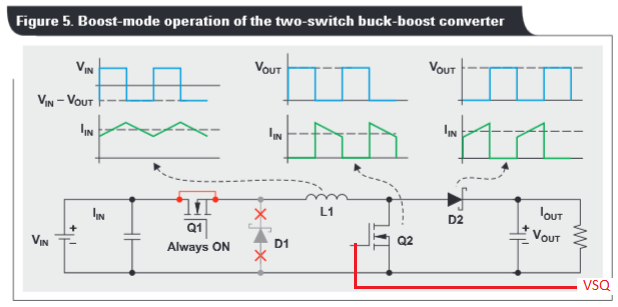
    I try to use the topology in below link in page 4 to build a non-inverting buck-boost  converter. I use 4 mosfets in the converter. For boost mode, the mosfet Q1 needs to be always on. I have tried several ways to drive the mosfet, but HO output can no longer keep the high side MOSFET turned on after maybe 10 seconds. I know it is because of the bootstrap capacitor discharged. So could you suggest a driver that can work in this topology?  In the PDF file in page 5, LM5118 is used, but I need a dual synchronous mosfet driver.  Do you have any suggestions?

    www.ti.com/.../slyt584.pdf

    Thanks again for your help

    Sincerely,

    Yuan

  • Hello Yuan

    Fig 8 and Fig 9 in the Data Sheet for the LM5118 clearly show that Q1 is switching in both the Buck and Buck/Boost modes. This means that its' bootstrap capacitor is recharged at every switching cycle. On the other hand the slyt584 diagram clearly shows the Q1 device ON during Boost mode and active during Buck mode. This is because the Buck/Boost mode described in the datasheet is different to the Boost mode described in slyt584. The title for Figure 6 is 'Two-switch buck-boost converter features buck and buck-boost operating modes' - this is not the same as the buck and boost modes shown in Figure 4 and Figure 5. Definitely confusing.

    The LM5175 is another device which controls 4 switches and operates in Buck and Boost modes.

    The idea I sent earlier - using a transformer to generate a bias rail for the bootstrap capacitor - should work for both devices. You just need to decide if the LM5175 or LM5118 are better suited to your application.

    Thinking about it - you could use one of the gate drive outputs to drive both a MOSFET switch and the primary of the transformer (VSQ) in the diagram. You need this transformer active during boost mode only, so you could drive it from the output used to control Q2 in the diagram.


    Regards

    Colin