This thread has been locked.

If you have a related question, please click the "Ask a related question" button in the top right corner. The newly created question will be automatically linked to this question.

Common-source/drain MOSFETs for dual pack selection?

Other Parts Discussed in Thread: BQ24616

Hi,

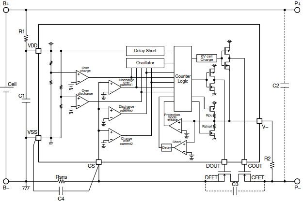
In an example battery protection circuit like in the image:

The protection used common-drain MOSFET pair at the low side. Is it because single MOSFET blocks only one direction current due to the body diode, so the common-drain pair is used?

In this circuit, does it make any difference if we use common-source connection for the same pair?


Extended:

We would like to use bq24616 to charge two 21V series. To completely isolate the two series, single MOSFET either at high or low end is not enough for the reasons above.

Could we use anti-direction MOSFET pairs to control which series to charge/discharge?

  1. Should common-source or common-drain be used?
  2. Should the pair be placed on the high side (bq→mosfet pair→battery→gnd) or the low side?


Hui

    1. It depends on how you plan on controlling the blocking FETs. Will you be using a battery protection IC to control the FETs? If so, then follow the application guidelines for that IC. In the image above, the configuration should be common-drain because they are N-channel FETs, and the pins of the IC are configured to control blocking FETs in a common-drain configuration. Putting them in a common-source configuration would reverse the control of the FETs during charging (CFET) and discharging (DFET). For  example, at cold temperatures (<0C), discharging of the battery may be allowed but charging is not allowed. This means that CFET is not conducting but DFET is conducting. The battery protection will control DFET/CFET according to allow charging or discharging.
    2. If you place the blocking FETs on the low side, then you can use N-channel FETs to control them with low voltage gate drive. if you place them on the high side, then you can do one of the following:
      1. Use P-channel FETs to control them.
      2. Use N-channel FETs with a charge pump to control the gate.

  • If using single pin to connect gates of the two low-side FET, the either common-source or common-drain would be OK (the same, as we only want completely OFF-ON state)?