This thread has been locked.

If you have a related question, please click the "Ask a related question" button in the top right corner. The newly created question will be automatically linked to this question.

Problem in configuring BQ34Z100EVM for multi-cell use.

Other Parts Discussed in Thread: BQ34Z100, BQ34Z100EVM, BQSTUDIO, BQ34Z100-G1

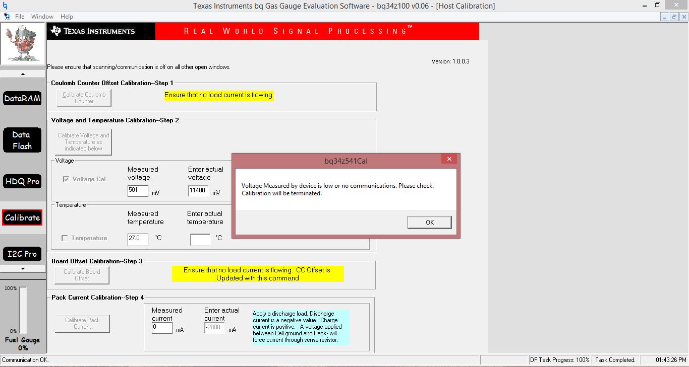
I am trying to connect a bq34z100 EVM with a EVM 2300 in Multi-cell mode with 4 cells. On connection to the PC and the bq evaluation software, the software does not display the complete value of the battery (4 cells in series). If I use a single cell to connect to the EVM, it shows the data correctly. On trying to write the registers, the data is not updating even after number of cells was changed to 4 (for multi-cell mode). Also I’d like to know how to configure the LEDs so as to indicate the SOC. I tried in the LED comm register but it didn’t reflect in the register. 

Thanks 

  • You will need to take these steps to configure the gauge for 4S and they need to need to be done before you enable IT. If you have enabled IT already, then you will need to reload the default senc file to disable IT first.

    • Set to the # of Series Cells parameter to 4.
    • Set the VOLTSEL bit in the Pack Cfg A register.
    • Calibrate the voltage. .

    The gauge should show the proper pack voltage now and you can configure other parameters. Enable IT after everything has been setup.

    Here is the senc file, in case you need it.

    https://e2e.ti.com/cfs-file/__key/communityserver-discussions-components-files/196/bq34z100_5F00_V0_5F00_06.senc

  • Thomas,

    I was able to complete steps 1&2. When I clicked on the Calibrate Voltage button, by setting the measured voltage, I got an error pop-up stating that "Voltage Measured by device is low or no communications. Please Check. Calibration will be terminated."

    I am very new to BQ34z100 and have no idea how to go about solving this issue. Please see the error message below. I would also like to make a correction, I have only 3 cells in series, not 4 as mentioned earlier. Sorry for the wrong information. Can you also please guide me with steps, on how the process of reloading the .senc file is done?

    Thanks,

    Badri

  • Badri,

    I assume that you are using the bq34z100EVM. Make sure that the jumpers are in the proper locations. The J5 jumpers should be in the >5V locations and the J2 jumper should be in the 16V location. If you have already attached the cells with the J5 jumpers in the <5V location, then the EVM is probably damaged.

    Since you are just getting started, I recommend switching to the bq34z100-G1. It is a firmware update to the bq34z100 and the EVM can be reprogrammed with the bq34z100-G1 firmware. You can download the firmware and bqStudio from the bq34z100-G1 website. 

    If you decide to stay with the bq34z100, then I would reload the senc file to make sure that the gauge is in a good state and then follow the steps that I listed earlier. I attached the old EVM User's Guide and it provides guidance on loading the senc file on page18.

    Tom

    sluu904.pdf

  • Hi Tom,

    I followed all the steps that you mentioned, but I am still getting the same error. Just to check I'm entering the correct values, on selecting the VOLTSEL bit, the entry into the Pack Configuration Register has to be 1161, right? I have 3 cells in series and have entered the same in the Num of Cells. When I enter the actual value in the Calibration screen, I get the error shown below.

    Please let me know if I am doing something wrong.

    Thanks,

    Badri

  • The VOLTSEL bit is Bit 11. It should be 0961.
  • Thanks for your reply Tom. I have corrected the register value to 0961 and the I was able to calibrate the voltage. However, I have a question about the LED register :
    If I want to use external LEDs with I2C comm, my Bits 0,1&2 will read 011, and assuming I make the LEDON (Bit 3 ) as 1; and if I want to display only 4 LEDs my code will be 0011. So my register should read 3B. Am I correct in assuming these values? If so, I tried writing these values, but the LEDs do not light up. I request you to please let me know what I am doing wrong here, as I mentioned earlier that I am new to BQ34Z100.

    Thanks again,
    Badri
  • Badri,

    The LED Config setting looks correct. Do you have the LED jumpers setup properly on the EVM?

    Tom

  • Tom,

    I checked the jumpers and there was an error in the setup. I have now placed only one Jumper at the EXT on J6. However, there are only 2 LEDs lighting up. If I change the value in the register to 6B, four LEDs are lighting up now. Is there any other configuration setting that I am doing wrong? Can you also tell me how to use the ALERT register, where to place the Jumper for what type of LED config etc,. Sorry to bother you with so many queries.

    Thanks,
    Badri

  • Badri,
    I checked this on the bench and found that setting the LED Configuration register to 2b will setup the device for four LEDs.
    Tom
  • Tom,

    I set the LED register to 2b and only 2 LEDs were lit up. On setting it to 6b, its setup for 4 LEDs. Kindly advise if I have to change any other register. Also please advise on where to place the ALERT jumper for the different alerts.

    Thanks,

    Badri

  • You should be using Pin 12 for the ALERT signal, so you will need to place the jumper in the D location on the J3 connector.
  • Hi Tom,

    Thanks for your reply about the ALERT pin.

    I was recording the data from my battery (3 cells in Series) but I was not able to see or record the current data. I am attaching screenshots and the data log for your reference. I had connected a headlamp to the battery in series with a switch so that I can record how it behaves in the presence and absence of load, but only the voltage changed. One more concern is that the SOC shows 43% throughout the whole recording time and also all 4 LEDs are lit up. Can you please throw some light on why I'm not able to record the current data and also the SOC and LEDs ? 

      Headlamp test.xlsx

    Thanks,

    Badri

  • Badri,
    Your log data clearly shows that you have a load based on voltage and temperature changes, but there is no current and passed charge logged. This would indicate that either the device or sense resistor network is broken. I would try applying 50mV across the SRN/SRP pins on the device to see if it registers any current.
    Tom
  • Tom,

    Thanks for clearing it up. Although I have one question, how do I apply a 50mV across SRN/SRP pins? Do you mean that I have to connect BAT+ and BAT-/PACK- and apply a 50mV across these two pins?

    Badri
  • Badri,
    You can use a power supply and just apply 50mA on the device side of the 100 ohm series resistors. It is usually easy to use the capacitor that is placed across the signals. Apply a voltage across it and see if the device registers any current.

    Tom
  • Hi,

    Can you let me know how the alert pin works? For example, how will I know if the LED is flashing due to over-voltage or overheating etc.
    How can I determine the fault and which LE is representative of that? I have the jumper on J3 now according to our discussion.

    Thanks,
    Badri
  • Badri,

    The ALERT configuration register allows you to set which FLAGs can set the ALERT pin. You will then have to read the Flags register to see which FLAG set the Alert pin.

    Tom

  • Hi Tom,

    Thanks for the solution. I have a few more doubts. If I am to use the BQ34z100 for my BMS, how do I tap the signals so that the values of voltage/current/etc are available to me so that I can display it on another device. For example, if I need to display the voltage on the cluster, what are the signals that I need to use.

    Thanks,
    Badri
  • The host can read the voltage, current, temperature, capacities, etc. over the I2C bus. The host can have some other device display the information.
  • Hi Tom,

    Thanks again for the reply. I have a few more queries.

    I am going to charge up a battery connected to the chip and it is currently in SLEEP or FULLSLEEP mode. Will the cell balancing commence on its own or should the chip be in NORMAL mode for Cell balancing to occur? Is there a "wake up" signal that should  be sent to the chip?

    Regards,

    Badri

  • Badri, 

    The bq34z100 does not support cell balancing. It is just a gauge. The gauge will wake-up from the sleep modes after current is detected. 

    Tom

  • Hi Tom,
    Is there a way to detect what mode the BQ34Z100 is in? Does it send out a signal or does it store a value in any register? If I have an application where the operational mode of one chip is based on the mode in which the BQ34Z100 is in, how do I configure that ? If I need to send a signal when my BQ "wakes up" from SLEEP mode, how do I communicate this to the other chip, based on what value or signal?

    Thanks,
    Badri
  • Badri,
    The device has three operational modes and then ROM mode. The gauge should not be in ROM mode, unless you send a command to enable it and you can check to see whether it is in ROM mode by reading something from I2C address 16. The device uses address 16 when in ROM mode and AA otherwise. The three operational modes are Normal, Sleep and Fullsleep. You can check to see if the device is in Normal mode by checking the Sleep flag or the thermistor. The Sleep flag will be 0 and the thermistor will pulse at a 1 second rate when in Normal mode. The Sleep flag will be 1 and the thermistor will pulse at a 20 second rate when in Sleep mode. Checking Fullseep is more difficult. You have to measure the current going into REGIN and you will see it drop when transitioning from Sleep to Fullsleep. The gauge will transition out of Fullsleep mode when I2C communication resumes and it will transition out of Sleep mode when the current exceeds the Sleep current.
    Tom
  • Tom,

    Thanks for the explanation. However, I need the bq34z100 to send out a signal whenever it comes out of SLEEP or FULL SLEEP mode. How can this be done ? Please let me know.

    Regards,

    Badri

  • The device does not have a signal to indicate that the gauge is in Sleep or Fullsleep modes. You can check for Sleep mode by checking the Sleep bit in the Control Status register. There is also a Fullsleep bit, but the gauge will exit Fullsleep if you read the register to check the bit.
  • Hi Tom,

    Thanks for the reply. Can you clarify a couple of queries for me ?
    1. Is it possible to know the cycle life from the bq34z100 ?
    2. What is the interval in which the device wakes up and measures data when it is in SLEEP mode or FULLSLEEP mode?

    Regards,
    Badri
  • Badri,
    I am not sure what you mean about the cycle life for the device. If you are asking how long the device can be used, then I will be fully functional for several year. Certainly as long as the battery is usable. The gauge takes current and voltage measurements every 20 seconds when in Sleep or Fullsleep modes.
    Tom
  • Hi Tom,

     I'm sorry, I should have been clearer in explaining the cycle life. I meant the battery pack cycle life. Is there a way to know how many times the pack has been charged/discharged, through the BQ34z100 chip. Is this value stored somewhere ? 

    Regards,

    Badri

  • The gauge has a CycleCount parameter that increments after a defined amount of Passed Charge is reached during discharge. The CC Threshold is usually set to allow the CycleCount to increment by one for every discharge cycle.