This thread has been locked.

If you have a related question, please click the "Ask a related question" button in the top right corner. The newly created question will be automatically linked to this question.

UCC28600 based 20W SMPS with 600VDC input

Other Parts Discussed in Thread: UCC28600

Hi,

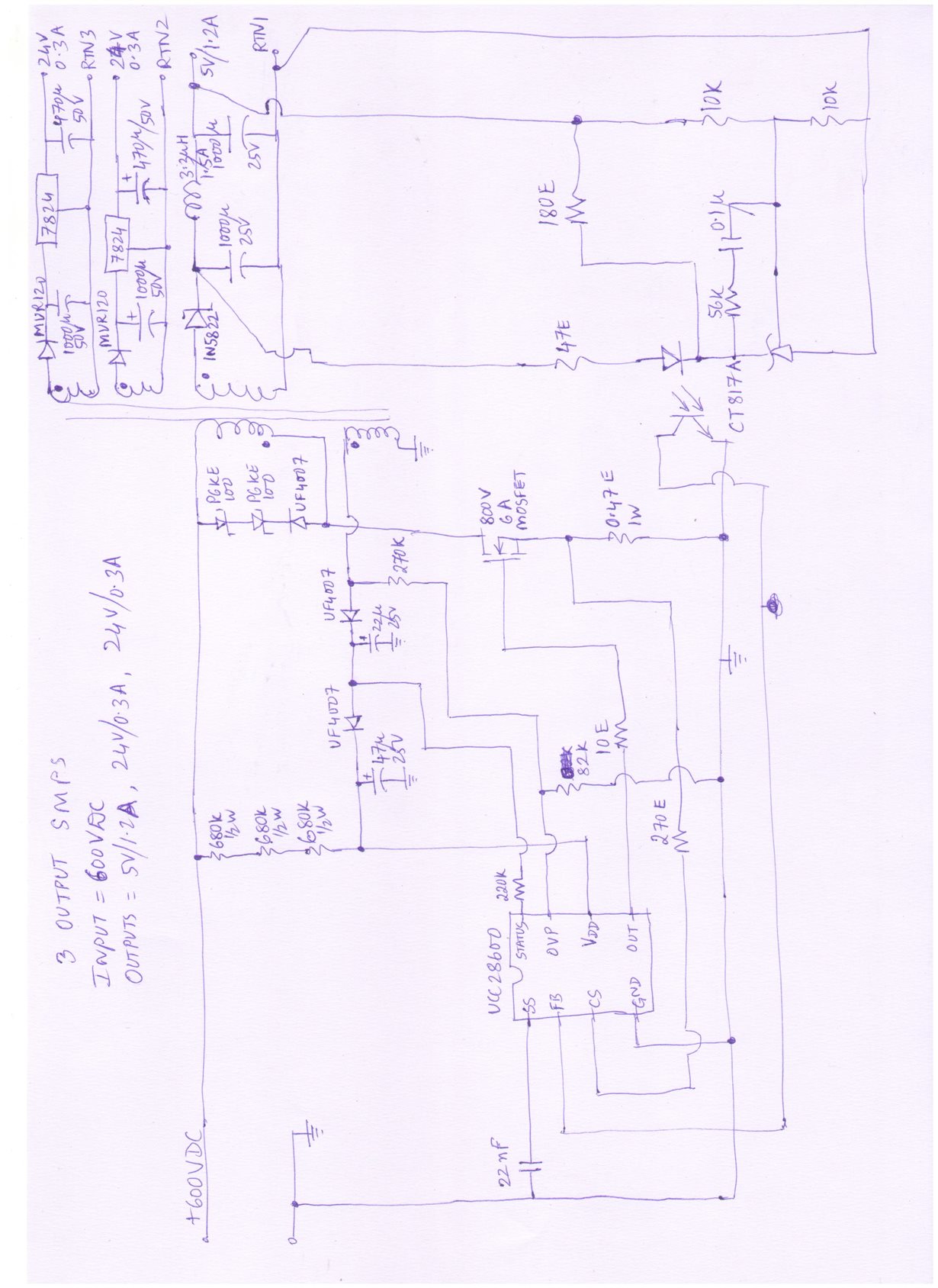
Given below is the schematic of a 3 output SMPS based on UCC28600. The SMPS was NOT working (output remaining 'low') with an input of 300VDC. Then I gave a fixed 15VDC to the VDD pin. Still the SMPS is not working - i.e. output is low.

Kindly let me know what are the causes for this 5v24v24v_UCC28600_EE2507.docx

  • There may be many reasons why the converter isn't turning on.  You need a small filter cap on FB (up to 390pF) to prevent noise, a small filter cap on CS (100pF may help), layout is critical as is transformer design.  You need to look at the waveforms to see what OVP, VDD, CS, SS, and FB are doing.  Use the design calculator used to select Rcs, Rpl, Rovp1 and Rovp2 and also to make sure the transformer has the correct inductance and turns ratio.  Refer to ww.ti.com/lit/an/slua399b/slua399b.pdf  for other considerations when using this controller.

  • Hi Lisa, Thanks for your valuable tips in 'handling' this issue with UCC28600. Is there a critical point in the basic schematic of a UCC28600 based SMPS that I need to check to ensure that the device is 'switching' ?
  • first I would check to see that, when the input voltage is applied, VDD rises to 15.3V (max turn on threshold), FB should go to 5V and SS should charge up.  When SS gets to 5V the OUT should start switching and FB should go from 5V to the appropriate level determined by the control loop.  If FB stays at 5V, SS is pulled down to ground, and VDD doesn't stay up above 8V then you won't get any switching.  Start at no load if possible. 

    Did you use the design calculator?  The combination of the Rcs, Rpl, and Rovp resistors is critical as is the transformer design.  You need to make sure that the design is within the operating parameters of the controller (on-time, frequency, OVP thresholds, etc.) and the design calculator helps there based upon the input voltage and output requirements.

    I just noticed you do not have a small (0.1uF) ceramic decoupling capacitor on VDD...this is required (non-negotiable, sorry...put it on there as close to the IC VDD pin and GND pin as possible...solder a leaded cap right to the IC right now until you can re-lay out your pcb...).

    Remove the 220k resistor from STATUS...you aren't using it for controlling the bias to a PFC controller and you don't have it configured for audible noise reductio so it should be open/floating.

    Did you add the filter capacitor to CS?  and one to FB?  noise on these inputs may be the issue. 

  • Hi Lisa, Thanks a million. This is the sort of information and tips that I was looking for.
    Regards
    Atul