This thread has been locked.

If you have a related question, please click the "Ask a related question" button in the top right corner. The newly created question will be automatically linked to this question.

TLV62130 short circuit damage

Other Parts Discussed in Thread: TLV62130, TPS82130, TPS62130, TPS62130A-Q1

Hi,

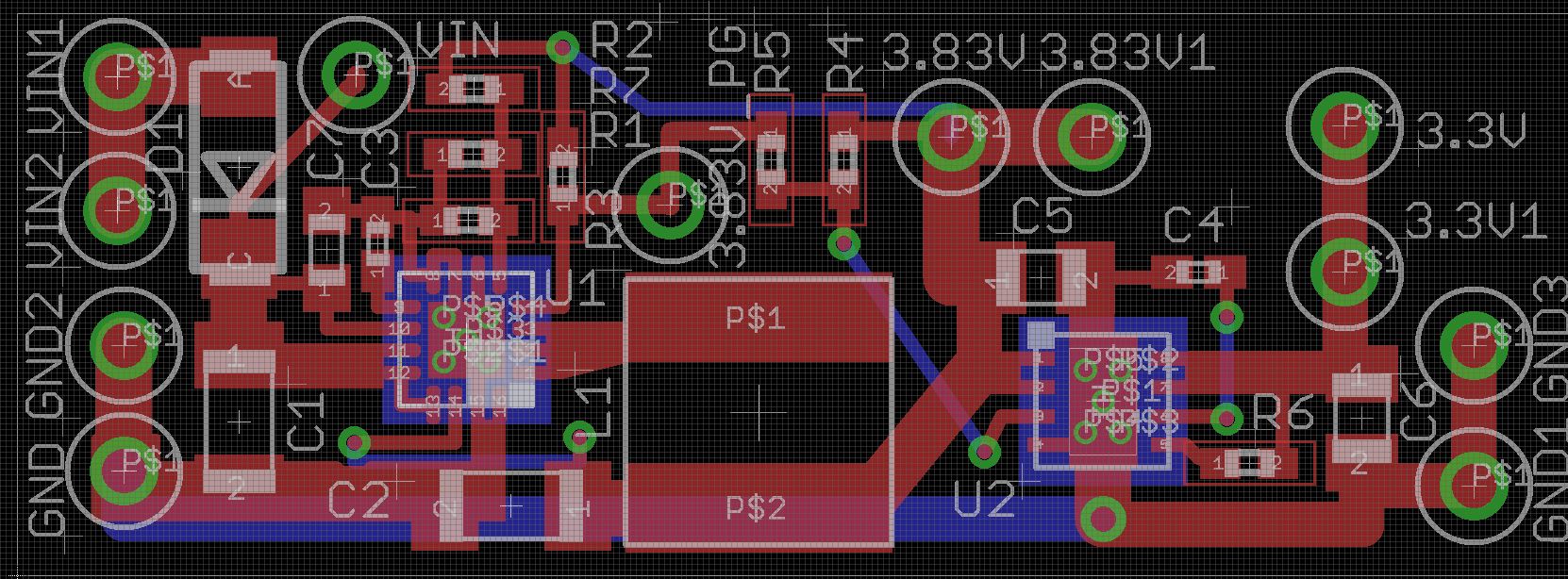
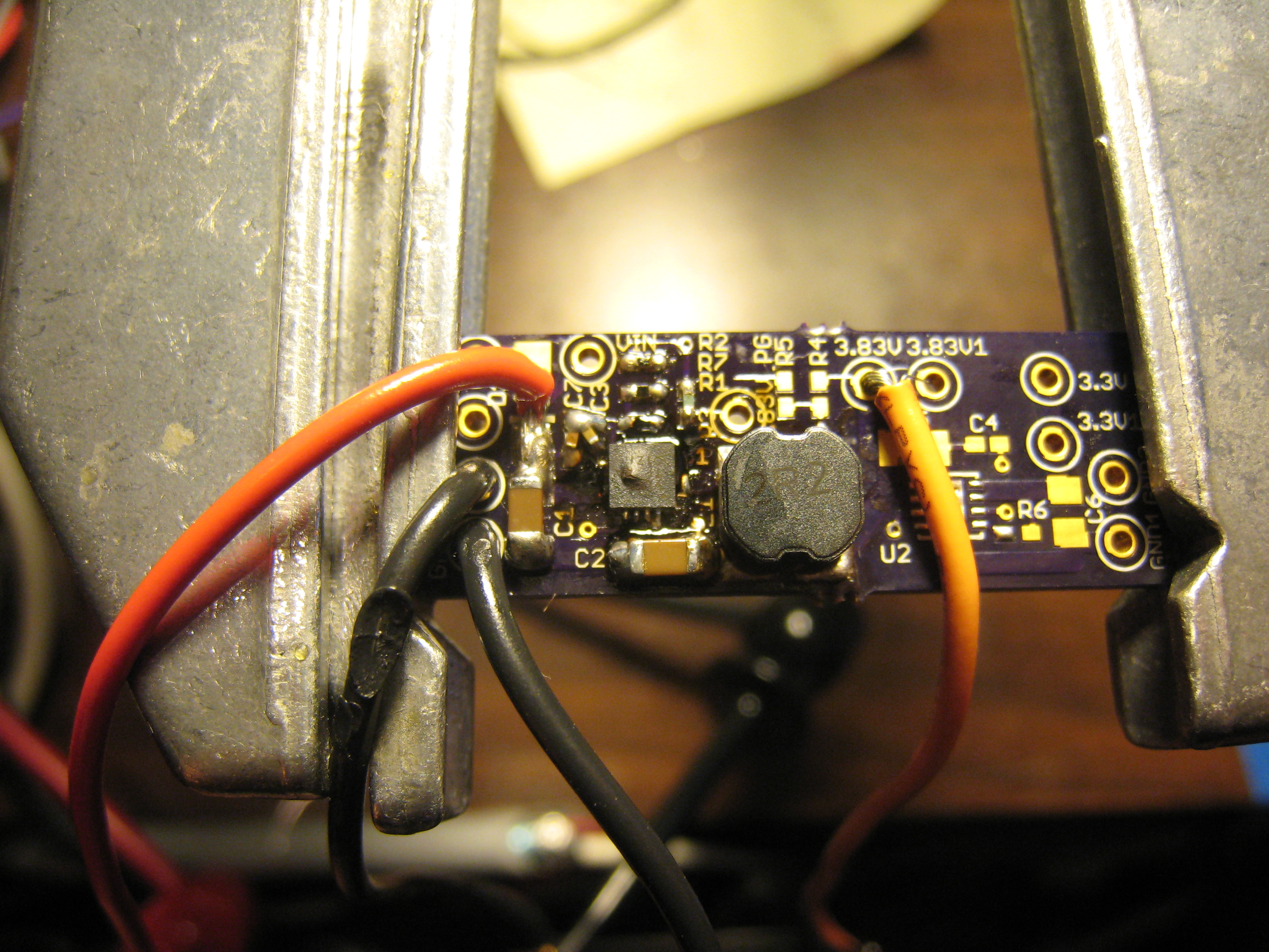
I am testing out the TLV62130 to potentially be used in our new product.

However, every time a short-circuit is produced across the TLV62130 output (i.e. not the MCP1727), the TLV62130 is damaged (the failure mode is typically either a very low voltage (~250mV, when set to 5V) or erratic output waveform).

There are expected small sparks when short circuiting the output, but I wouldn't imagine this to be the cause of the damage.

We had planned to use the TLV62130 along with a MCP1727 LDO, so I included both here for completeness.

We currently are using a 6 ohm dummy load on the output.

Is there any way to prevent the short-circuit damage?

Much appreciated!!!

Justin

  • We are going from ~14V to 5V on the TLV62130 (not 3.83V, as labeled on the schematic / layout test points).
  • Thanks for posting your schematic and layout. Do you have a waveform of Vin, Vout, SW, and inductor current when you apply the short and then again when it isn't working? What inductance do you use?
  • Thanks for the fast response, Chris.

    I will try to put another IC on the board and get the data you request.  Do you have a recommended way to get the inductor current, given the schematic posted?

    We are using Bourns SRN6045-2R2Y - 2.2uH, 30%.

  • To measure the current in the inductor, you need to remove the inductor, solder one end of it to the SW pins, and put a wire in series with its other terminal and Vout. Clip a current probe around this wire.

    You might try adding some bulk input capacitance at the input to your board. With just the 10uF ceramic and powered from an AC adapter or lab supply (how do you power your board?), there are likely ringings and overshoots on Vin from the long cables from the input supply to the PCB.
  • We have a 100uF low-ESR electrolytic cap further upstream, hopefully that will help with the Vin overshoots. We are currently powering via a lab PS (which on the scope hasn't shown any spikes of note). However, we have had random TLV62130s go dead on our actual application, which is powered by a automotive power system (alternator + battery). We will probably put TVS diode before the TLV62130 to help avoid this (assuming a Vin spike was the cause of the failure), unless you have another recommendation.
  • Yes, a TVS or some protection circuit is probably required in such an application.
  • Does the waveform below look correct?  I finally have a TLV62130 on board that seemingly isn't blown, but not sure about the waveform.  Yellow is Vin (~13V), Blue is SW, Red is Vout.

  • The pulses on SW should be evenly spaced. I suggest adding another 22uF output cap to overcome the DC bias effect.
  • Hi,

    I suspect you need a bigger inductor than2u2H and 6045 size as the inductor may well be saturating before the IC can current limit. Can you please advise the batch code line 2 underneath the part number, indicating the week number the device is manufactured?

    Thank you.
  • Hi Ali,

    Well, if 2.2uH is too small, then TI needs to revise their datasheet and website, as we used the exact recommended inductor from the Webench tool.

    The markings on the IC are:

    VUBI

    31

    C4KI

    Thanks,

    Justin

  • Hi Justin,

    Sorry for the misunderstanding, if you are running at 2.5MHz 2u2H may well be OK however physical size/construction of the inductor may cause saturation before the current limit kicks in. This is a little speculative as we are having a problem largely with parts from Wk33, yours look like it is Wk31. I have not been able to find the root cause except to point the finger at the batch/yield of these devices.

    Regards.

    Ali
  • Hi Ali,

    No worries - yes, we are running at 2.5MHz. We've been side-tracked with other issues for now, but have had more PCBs made to re-check this issue in a few weeks.

    I can't speak to what's causing it yet, whether it be a manufacturing or fundamental design issue. Or perhaps an insufficient inductor specification as you mention. It's been my observation that certain short circuit events cause it to burn while others don't. We haven't figured out what the difference between those events are as of yet.

    Thanks for the post, and please let me know if you're able to make any progress!

    -Justin
  • Hi Justin,

    The inductor you are using is fine. The even at 6A you still have about 1.5uH of inductance. This is clearly not the problem.
    Could you please share some more details about your setup. What is the part number of the input capacitor? What is the distance between the 100uF Bulk  and the input capacitor after the diode?

    One thing you could try is to increase the input capacitance by adding an other ceramic cap at the board and get the 100uF as close as possible to the board.
    There seems to be a lot of noise on the input, SW and also Vout. Could you please share a picture of your bench setup?

    Regards,

    Anton

  • Hi Anton,

    Sorry for the late reply - I had to order more PCBs from continually replacing the TLV62130s until the pads gave out, then got busy with other stuff.

    I recently started testing again, trying to keep a better record of the configuration of each burned TLV62130.

    Three burned relatively quickly today (this a new lot of TLV62130s than before, FWIW).

    To create the short circuit, I have simply connected a cheap switch (i.e. likely bouncy) to the output and ground (it doesn't seem to matter whether a load is otherwise connected or not).  I open and close the switch repeatedly.  I can occasionally see spikes (which I assume is from the inductor) on the output when I open and close the switch, but nothing higher than 15V that I can capture.  After several iterations of shorting the output, I will get a burned TLV62130.  The failure mode is short to ground.  If I don't quickly turn off the power supply, it will put out its max 5A and the TLV62130 will sometimes start smoking (see picture below).

    The input voltage is 14V.  I even connected a low ESR 100uF electrolytic in parallel with the 10uF ceramic cap (not shown in the pic), but it didn't seem to make any difference in the IC being destroyed.

    I am using a standard lab power supply with 18" leads.  This is a lot better configuration than our product will have in the field, so please let me know if the TLV62130 can't handle much input inductance.

    I would really like to use this part, as it has the form factor, switching frequency, efficiency, etc. I need.  But unless someone can provide an answer as to why it keeps burning, it would be poor judgement to go with this part.

    I look forward to your (or any TI representative's) response.

    Thanks!

    Justin

  • Hi CJ,

    I'll need to see some waveforms to fully understand what is going on. The waveform I need ideally is when the converter breaks. Could you probe Vin, Vout, SW, and the inductor current at maybe 20usec/div? Trigger on Vout falling to see the moment when it breaks.
  • This question is similar to what I am looking for, and your writing style is similar to mine. For a second I thought I had asked the question back in April. I struggled to recall the circuit and layout. It took me a few seconds to realize it wasn't me. It's weird.

    Regards,

    CJ Gervasi
  • Thanks for sharing the details on the other thread. It was unclear to me that the above circuit was being damaged with a DC load applied.

    I would expect damage to it when powered from a car battery due to the voltage spikes. A TVS may help but its clamping voltage and power would need to be checked.

    If you are applying the output shorts in the above picture through the yellow and black wires, this inductance is likely causing voltage excursions on Vout outside of the IC's ratings. You could measure the voltage across C2 and see if it ever goes below ground or above 7V. These inductive shorts are typically lab setup related as the load is located on the same PCB as the power supply in most cases (and therefore has much less inductance in its path).

    If you are still having random issues with a DC load, then I could evaluate a picture of this setup as well as your operating conditions (Vin, ambient temp, anything special in your setup) to debug. As well, could you send the part numbers of C1 and C2 which you have been using (I assume these have not changed?)?

    Finally, since this thread began, we have released the TPS82130 module which significantly reduces the total size of this type of solution.
  • To try to clear things up a bit, there are two issues, which may or may not be related.

    1) "Spontaneous death" - in normal usage, with a light load (i.e. TLV62130 sourcing about 0.5A), the IC will mysteriously "die" after varying lengths of time. Usually a few weeks (of 6 hours/day business day usage) will go by before it stops working.

    2) "Short circuit / burn death" - in response to #1, we tested the short circuit performance of the TLV62130, assuming at first that the "spontaneous deaths" must have been caused by some short circuit we didn't notice. The subject of this thread was in response to #2, "Short circuit / burn death"

    Yes, the yellow (orange) wire was used to connect to ground via a switch in order to short-circuit the output. The wire was a few inches (<6") long. Correct me if I'm wrong please, but you're suggesting that the impedance from a wire of this length could cause a voltage excursion outside what the TLV62130 can handle in a short circuit event, which may lead to the 'burn' failure we see, correct? If this is the case, this definitely isn't the regulator for us, as our product has sensors connected to it (GPS receiver, for example) that have wire connections several feet in length. I will investigate the Vout excursion with these inductive shorts, as you suggest, thank you.

    Regarding the random issues with the DC load (i.e. "spontaneous death"), as previously mentioned, there are sensors that are powered by the TLV62130 via wires that are several feet in length. However, these wires never short-circuit when the "spontaneous death occurs". And the TLV62130 doesn't show any physical signs of any issue (such as burning or smoking, etc.). It just stops working. The last time it happened, the switch waveform was captured, and it showed only two pulses per 'period' (versus continuous pulsing). So, there was a very slight voltage on the output (barely measurable - maybe 0.1 or 0.2V). I would like to share pictures of the setup, but unfortunately there's a lot of proprietary stuff that I can't post online.

    The TPS82130 you reference looks pretty great in terms of specification; it certainly takes very little board space. But ultimately, reliability is paramount for us, so I would assume it would have the same issues (for us, anyway) that the TLV62130 regulators have. Do you know what the difference is, between the automotive-specified TPS62130A-Q1 and the TLV62130 is? Would you expect that it would be any better for us in terms of the issues we're having? Is it a safe bet that powering devices several feet in wire length downstream is inadvisable for a product like the TLV62130 / TPS62130 series?

    Thanks!
  • No, the capacitors didn't change. C1 = Taiyo Yuden TMK316BJ106KLHT; C2 = Murata GRM21BR61A226ME51L. The setup is in open air, room temperature.
  • Thanks again for clarifying and continuing to dialogue on this issue.

    The issue with inductance in the output leads is the ringing created. Instead of just Vout and GND, now you have an LC circuit which can ring up and down--above 5V and below GND. For the TLV62130 and for most ICs, the absolute maximum ratings in the data sheet prohibit most pins from being taken a diode drop below GND. The ringing from the cables could cause this to happen. It's worth checking on your board. Are the wires a twisted pair?

    It's interesting that in the one failure you noted, the IC still switches. When it spontaneously dies, does it always fail this way? Did/could you Ohm out the SW pin to GND and measure things like FB, SS/TR, SW in operation (when it's not working right)?

    How much input capacitance is at your sensor input at the end of the cable?

    Did you try adding another 22uF output cap next to C2? The SW node waveform you shared earlier showed an irregular spacing. This can be caused by not enough output cap, which is likely since the 5V output voltage creates quite a bit of DC bias loss.

    I don't believe a different device from this family will affect the behavior you are seeing.
  • Thanks for the ongoing support, Chris.

    No, the wires are not twisted pair per se (i.e. for differential signaling), though they likely gradually twist as part of a multi-conductor cable.

    I don't recall the state of the SW output in previous failures, as usually the failures came at an inopportune time and less time was spent diagnosing than replacing. Though we are transitioning to another device, I will try keep running this one to get another failure and measure the pins you mentioned.

    In terms of capacitance at the end of the sensor cables, in total it's probably at least 20uF (input capacitors for ldo regulators), though some of the sensors are 'black boxes' to us, so I don't know off hand. There's no ringing in steady state, but would obviously expect some in a short-circuit scenario.

    I can't recall if I added another output cap or not. I will add this to the list of items to try.

    Can you clarify what you mean by "the 5V output voltage creates quite a bit of DC bias loss"?
  • Larger value ceramic capacitors like these have a 'DC bias effect' whereby the actual effective capacitance in the circuit decreases as the DC voltage applied on them increases. This is shown in each of the data sheets for the caps you are using. 5V is a rather high voltage and so yields significant loss of effective capacitance. This is one possible cause of the SW waveform you showed earlier. I recommend adding 1 more 22uF at the output and seeing if the SW node becomes more regular.
  • I added the same 22uF ceramic cap to the output. but the SW waveform didn't change at all.  I even added a 100uF alum electrolytic for fun with the same results.

    One note - the regulator is being significantly underutilized at the moment - only pulling about 200mA at 12V.  Not sure if this makes any difference in terms of the "spontaneous death" failures.  If I remember correctly, we used a heavier load in our short-circuit testing , and it always had uneven SW spacing.

    Let me know if you have any other ideas.  In the meantime, I'll be waiting for another failure, and will measure the signals and report back when it does.