This thread has been locked.

If you have a related question, please click the "Ask a related question" button in the top right corner. The newly created question will be automatically linked to this question.

TPS62130 Damage

Other Parts Discussed in Thread: TPS62130

It looks like the TPS62130 device in our design is getting damaged when the input supply is removed. I suspect that the voltage on the SW pin is exceeding the rated maximum of Vin + 0.3 when the input voltage decays quicker than the output voltage.  Is this a vulnerability of this device. If so, would you recommend a shottkey diode connected in reverse from output to input, like some of the older linears used to need?

  • This is not usually necessary. Could you post your schematic and PCB layout? Can you get a waveform of Vin, Vout, SW, and inductor current when it fails?
  • Chris,

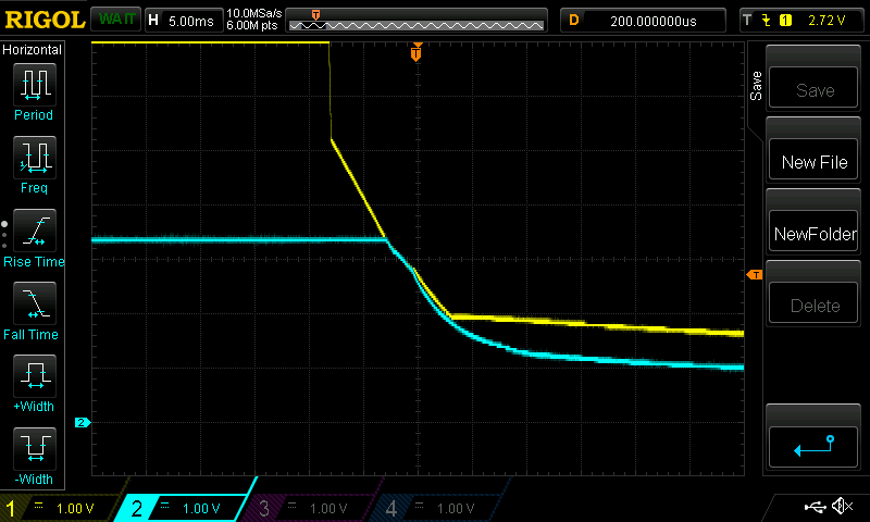
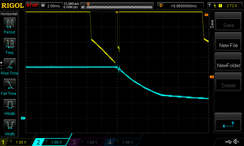
    The layout and schematic are exactly out of the data sheet.  If there is a private channel, I would be willing to send more information regarding that.  Attached are some scope waveforms.  Failure does not occur every time.  If you look at the attached you see the input in yellow and output in blue. They use the same scale and same offset. The input is 12V, but this is off screen so it looks like 7V. When the input supply is disconneted, there is a fast discharge to about 5.2V. I think this is due to another similar TPS62130 that is regulating 5V to another load. Then the 12V decay is slower. The output is always less or the same as the input.

    In the second shot, it looks like there was a little contact bounce when the power was removed.  The part failed this time.  Does this help?  Thank you, Don

  • You could just post a screenshot of the relevant portions of your schematic and layout here or you can send me a message through the link in the top right corner of the browser.

    Let's look at the whole Vin in the above trace when it rings up. You could trigger on Vin going very high (>15V for example) at a short timescale. 10 usec/div for example.