A related question is a question created from another question. When the related question is created, it will be automatically linked to the original question.
If you have a related question, please click the "Ask a related question" button in the top right corner. The newly created question will be automatically linked to this question.
Inaccuracy in LM5050-1 and LM5050-2 transient models for TINA?
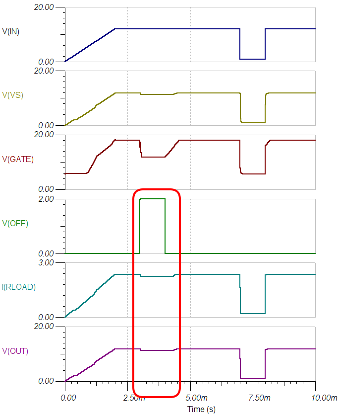
Is it possible that TINA transient models snmv061 (LM5050-1) and snmv063 (LM5050-2) have problems with simulate Voff condition? Here is what I got when start mentioned transient analysis for mentioned models:
Hello Denis,
That is possible, Please allow more time for the OFF condition and have the load at the out to discharge the output cap. Please note when you turn of the MOSFET buy OFF Pin (Pulling the Vgate low ), the MOSFET's, the power flows thru the body diode of the FET.
There is no output capacitor. Anyway what is a right way to deploy OFF pin? It's stated that A logic high state at the OFF pin will pull the GATE pin low and turn off the external MOSFET. I forgot how mosfet is wired here and that body diode can conduct. In this case it seems that purpose of OFF pin is not to isolate power source from the load. Sorry, I just trying to figure out to what extent LM5050 is suitable for my project (I have possibility to switch off PSU's outputs before ORing).
The gate turn off pin could only be useful if two FETs and two LM5050-1 were used as a solid state relay, if that is even possible. I have not tried. Otherwise the turn off feature is pretty useless as the intrinsic diode will take over conduction and defeat the purpose of the chip, to eliminate the losses of this diode. Perhaps useful if you needed some heat generation;-)
Looking back, I saw that in an earlier post you had mentioned that the LM5050 only produced a ~2V gate voltage depending on input voltage when you were testing it.
That is because the PSMN1R2-30YLC is a 1.2mohm FET. The LM5050 regulates the Vds to 22mV. So with a 1.2mohm FET, it will lower the GATE voltage, causing the Rds-on to rise, until there is 22mV across the MOSFET.
If you connect the same circuit but run >20A through it, then you would see the MOSFET fully enhanced.
If you have any more questions about this part, or other devices we may have which may be better suited for your application, pleast start a new thread within "Power Interface" and we can help.
I did find that after a couple of hours of testing. I had expected the gate voltage to snap like a Schmitt on load sensing. 2.5A thru the 1.2mOhm device was obviously not enough to fully enhance the gate. However, I'd expect an important aspect like this would be described in a graph, rather than describe gate voltage a "7 - 14V" .