This thread has been locked.

If you have a related question, please click the "Ask a related question" button in the top right corner. The newly created question will be automatically linked to this question.

TPS62152 operation with an SVS

Other Parts Discussed in Thread: TPS62152, TPS3803, TPS62125

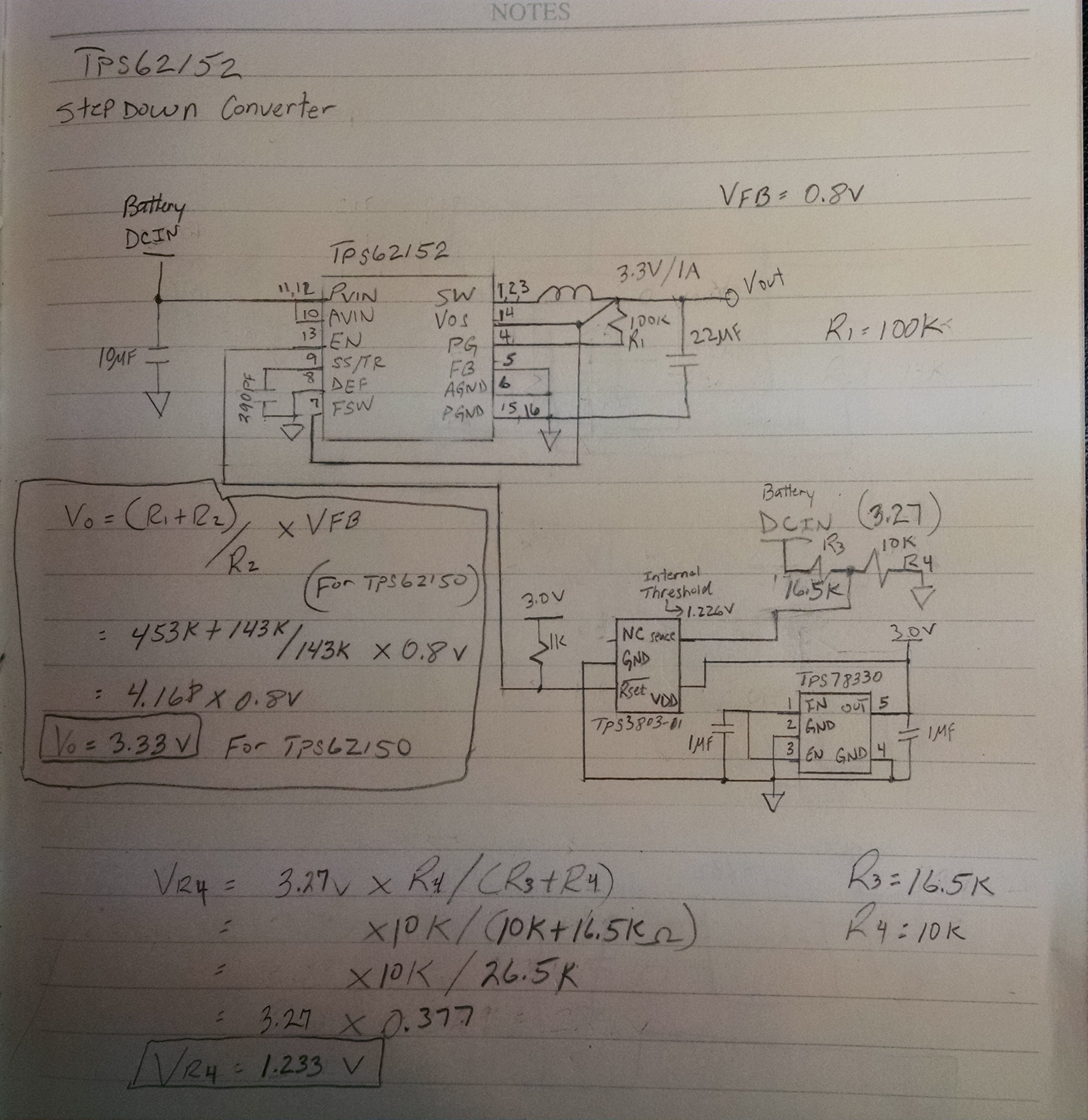
I am using the TPS62152 step down converter to regulate 3.3V and I want to disable this converter at a certain voltage level. I am using the Voltage Detector TPS3803-01 to detect that voltage threshold. I connected the enable pin of the converter to the reset pin of the voltage detector that should disable the converter once the threshold is reached instead it made the converter operate strangely. With the enable pin of the converter tied to PVIN and AVIN I can operate my circuit from 6V down to 3.5V, with the enable pin of the converter going to the reset of the detector I can only go from 6V down to 4.2V. And once I took the enable pin off PVIN and connected it to the detector I noticed it was drawing 100mA of constant current I replaced the device with the enable pin connected to PVIN and AVIN and all was will I was down to 8mA and the range was 6V down to 3.5V. I then took the enable pin off of the PVIN and connected it to the reset pin of the detector and after a few minutes I started drawing 100mA again and when I connected it back to the PVIN the 100mA was still there. I believe I damaged the converter when I took the enable pin off of PVIN/AVIN. My question is:

1. Does the enable pin of the TPS62152 have to be connected to PVIN and AVIN?

2. To disable this device does all three (3) pins, PVIN; AVIN, and Enable have to be connected to the reset pin of the TPS3803-01?

3. Why is the TPS62152 failing when I disconnect the enable pin from PVIN and connect it to the reset pin of the TPS3803-01

Thank you.

Jeff

  • 1. No
    2. No. Just connect EN to an open drain output with a pull-up resistor.
    3. Please post waveforms of Vin, EN, Vdd to the SVS, and Vout showing what you describe.

    You should be able to use an open drain SVS like this to do what you want to do. I'll note that the TPS3803 can only operate up to 6V, so it likely cannot be powered from the same voltage as the TPS62152. As well, an open drain output requires a pull-up resistor to register a logic high.

    The pull-up resistor cannot go to the TPS62152's Vin as this would apply that >6V voltage to the SVS, which it is not rated for.

    As well, if EN is driven high while PVIN/AVIN is not present, you have violated the abs max rating of the EN pin and might damage the device.

    Finally, the TPS62125 has an SVS built in basically, if you just need 300 mA.
  • Hey Chris,

    I am using a 3V regulator to power up the TPS3803. I have a voltage divider on the sense pin that drops reset low when the voltage threshold level is reached. The TPS3803's output is connected to a pull up resister to 3V and that output is going to the enable pin. I do not have a pull up resister on Vin. PVin; AVin and EN are connected directly to my source. Please find attached the pictures of Vin; EN; Vout of the TPS62152 and VDD and Vout of the TpS3803-01. and also the schematic. Trace 1 is TPS62152 PVin/AVin, Trace 2 is Vout, Trace 3 EN and trace 4 is VDD of the TPS3803-01. I am a little hesitant to connect this detector to the enable pin because I already damaged 3 devices. I will try one more time and get those waveforms for you however; if it still doesn't work for me I will use a load switch and let the detector gate it and EN will see the same source as PVin and AVin then when the threshold is reached and reset goes low the load switch will be disabled. I soldered the leads directly to the device per data sheet.Thanks Chris I'll keep you posted.

    Jeff

  • I'm not understanding how PVIN/AVIN/EN are all connected together and then you connect just EN to the output of the SVS (instead of having it connect to PVIN/AVIN). Do you have a jumper or something on your board or are you modifying the PCB with a cut, etc.? Perhaps posting a partial schematic will help.
  • Chris, I do not have an Evaluation board, I have the QFN chip and just soldered directly to them and soldered the leads to my prototype board. Thanks.

    Jeff
  • I'm still not perfectly clear. Could you post the prototype layout you are testing on?

    Would it be possible to trigger on EN going high and low in those waveforms? Ideally, you could make a capture at the moment it fails.
  •  Chris,
    I am not triggering on enable, enable is tied to power in, just as the PVIN/AVIN (10;11;12;13). What I am trying to do is to remove enable off of PVin so I can control it. I want to send enable to the voltage detector so I can shut down the TPS62152 at a certain voltage but when I connect enable to the reset pin of the TPS3803-01 I draw 100mA of current that was not there before when it was connected to PVin and when I put enable back to PVin the 100mA remains. Somehow the device is failing and I don't know why.

  • Oh, this is your PCB. This will not work for a switching power supply. There is way too much inductance from those wires and connections to get reliable operation.

    There may be something else with your SVS affecting things, but you need to order an EVM and test the SMPS on a known good layout. The above may work for some linear circuits (LDOs, SVS, etc.) but not a switching circuit.
  • OK got it, I'll get an EVM board. Thanks Chris.


    Jeff