This thread has been locked.

If you have a related question, please click the "Ask a related question" button in the top right corner. The newly created question will be automatically linked to this question.

UCD9090 will not activate outputs

Other Parts Discussed in Thread: UCD9090, UCD9244

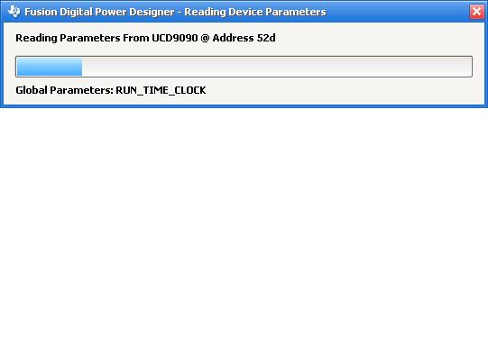
We are using a UCD9090 sequencer where the UCD9090 monitors a few voltage rails and general purpose inputs and activates a few general purpose outputs based on the inputs and monitored voltages. On one board occasionally the UCD9090 does not activate any outputs even though all inputs are at valid levels. I connected this board to a USB interface adapter and attempted to use the Fusion Design tool to see what was going on with the UCD9090. When the USB interface adapter is connected, the UCD9090 will never activate outputs. The part is somewhat functioning. The Monitor in the Fusion Design GUI does show valid values for the inputs, so I2C is working and the part is correctly reading the voltage rails being monitored. Also, there is a window that continually pops up in Fusion Design that says Reading Device Parameters. This does not happen if the UCD9090 is functioning correctly. We have observed this behavior on only one of a few prototype boards. Any ideas what might be causing this situation?

  • Please provide a project file which is saved immediately after the problem happens. From the project file we can see what is preventing the power sequence from start in the device.

    Please also provide a screenshot of the pop-up window.

    Thanks.
  • The project file and screenUCD9090 @ Address 52d Project.xml shots are attached.  Thank you.

  • I see a System Watchdog Timeout fault. The System Watchdog does not have I/O pins assigned to it. If you did not configure it on purpose, you can disable the watchdog and see if the problem is solved. 

    Thanks,

    Zhiyuan

  • The watchdog was enabled intentionally and configured correctly. I disabled watch dog, but this did not fix the problem. Apparenly I forgot to re-assign the IO pins when I re-enabled the watchdog.
  • OK. Let's try a few things to identify the problem.

    How many PMBus devices are on the bus?

    When use FUSION GUI to connect to the device, is there another PMBus host talking?

    Please try disable runtime clock and see if there is improvement.

    Also, please enable Reset Tracking function.

    After enable reset tracking, please also clear all faults and logged faults, and run the device for a while, and then check how many times did the device reset. Please save a project file and send to me.

    Thanks,

    Zhiyuan

  • There are only 2 devices on the PMBus, the UCD9090 and a UCD9244.  The FUSION GUI is the only host.

    I powered the board without the FUSION tools attached, and the UCD9090 functions normally.  I then attached the FUSION tools, disabled the watchdog, disabled the run time clock, cleared all faults and logged faults, and then enabled reset tracking.  I let it run for a few minutes, and only the initial reset was recorded.  There were no faults were indicated.

    I then power cycled the board with the FUSION tools attached.  The UCD stopped functioning.  I verified that the watchdog and run time clock were disabled.  There is a watchdog error in the logged faults even though the watchdog is disabled.  I then enabled reset tracking.  The UCD9090 is continually being reset.  I then saved the project file.  The project file is attached.  I opened the project file in the FUSION offline tool and noticed that only 2 of 5 run time check boxes were de-selected even though all 5 were deselected when connected online.


    7026.UCD9090 @ Address 52d Project.xml 

  • Hi Matt,

    Can you try GUI version 1.9.78 and see if the problem persists.

    Thanks,
    Zhiyuan
  • Same results with 1.9.78. The board does show the same behavior sometimes even wihout the fusion tools attached.
  • What are the voltage and current measured on the PMBus Clk and data? What are the USB Adapter setting (you can find the info using Fusion GUI->File menu -> USB Adapter Setting)?

  • The I2C signals are pulled to 3.3V with 4.7K resistors.  I changed to 1.2K pull-ups, but the results are the same.  The I2C communication is successful when the UCD9090 is in the state where it continually resets.  The USB adapter setting are attached.

  • What about the power consumption? Is it above 450mA?

    Can you save the data flash using the Low level Debugging Tool (UCD3XXX/9XXX Device GUI tool from Start menu -> Texas Instruments Fusion Digital Power Designer -> Device GUIs) and send to us?

    • Click on "DEVICE_ID" link to detect the device
    • Select "Flash" tab, and then click on "Export Flash". Follow the instruction on the screen

    After saving the data flash, try to erase the data flash and re-download the project file to see if the issue still there. Using the same UCD3XXX/9XXX Device GUI tool to set the dFlash to 0xFF.

    • Click on "Command Program to jump to ROM...". If success, the "Set DFlash to 0xFF" should be enable. Click on the "Set DFlash to 0xFF" should erase the data flash and set it to all 0xFF.
    • NOTE: After erase the data flash, you must re-create the program flash checksum (checksum is erased when you send the device from Program Mode to ROM mode in the above step). To recreate the pflash checksum, use the "Checksums" tab, "Recreate" link. And then send device from ROM back to Program mode by click on the "Command ROM to execute its program..."

  • What power consumption are you looking for? Is this reported by the FUSION GUI somewhere?

    I tried to export FLASH as you suggested, but the tool says this is a protected feature that requires a password. I do not have the password.
  • The power source input to the device, what are the voltage & current measured? It is not reported on Fusion GUI. The pwd is "forestln".
  • The UCD9090 is powered by 3.323V.  The current draw on the 3.3V regulator is 590mA, but there are several other components being powered by 3.3V.  I have no way to measure the current being drawn by the UCD9090 unless I cut traces on the board.

    I followed the export flash procedure, and the hex file is attached.  I erased the flash and then reprogrammed the part.  This did not fix the problem.


    UCD9090_flash.zip

  • Hi Matt,

    If you replace the device with a new one, does the problem persist?

    Thanks,
    Zhiyuan
  • I replaced the part.  The new part has not failed yet.  Any ideas what might have caused the original part to fail in this manner?

  • Matt,

    We cannot tell at this moment. Did the part ever work correctly or didn't worked from the beginning? Was the device properly handled/soldered during assembly? Let's wait and see how the new part doing. If necessary, you can return the device for failure analysis.

    Thanks,

    Zhiyuan 

  • Matt, did you try placing the faulty part back into the same system board or another system board to see if the problem returned, it may have been a soldering issue. Good to check this before returning a part for failure analysis.
  • No, I did not place that part back on a board to see if the problem returned.  However, we have another board that has similar behavior.  We did xray to check the solder joints, and all looked fine.  We then reflowed the part and did xray again.  The soldering looked fine, but the part still failed.  Next we will replace the part with a new one.  If the board works with the new part, then we would have two bad parts we can return for FA.

  • The second board has not yet failed after the UCD9090 was replaced.