This thread has been locked.

If you have a related question, please click the "Ask a related question" button in the top right corner. The newly created question will be automatically linked to this question.

BQ24075TRGTT Burn problem

Hi all,

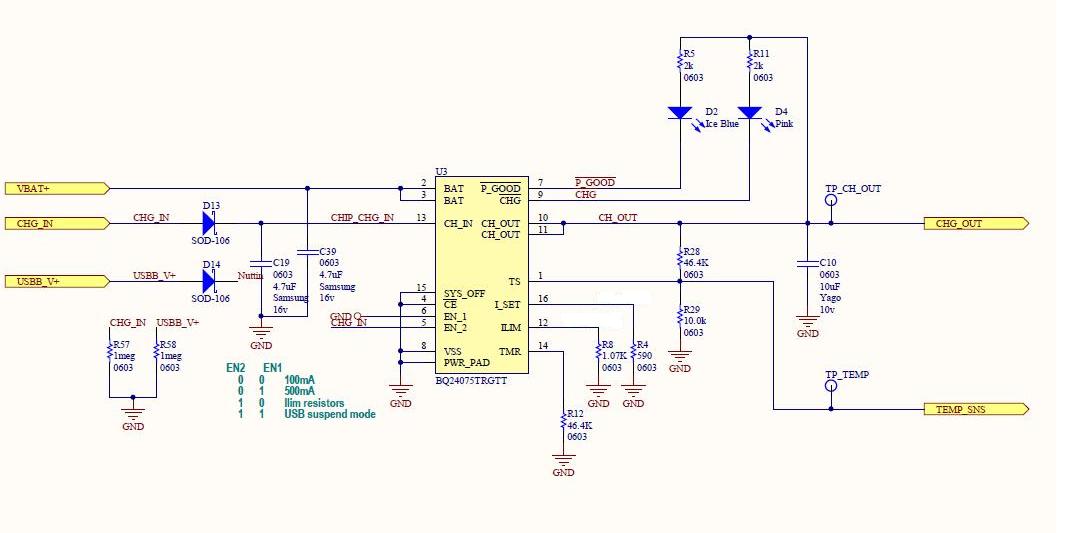
I have a design with BQ24075TRGT implemented on it. I encountered the following problem:  after about 2 weeks of use the   BQ24075TRGT stops charging. When I replace the charger IC on the malfunctioned board, it starts charging again, so from this I understand that the malfunction part is the IC itself. the input current is limited  to the maximum current of the IC (1.5A~) , and the charge current is also set to 1.5A~.

The practical measured current on the circuit is 1A total, half of it charging the battery.

My question is:

Did anyone encounter such a problem?

Can anyone suggest a reason why the IC keeps burning like this.

Thanks in advance

  • You mentioned that the charging current is set to 1.5A so what did you mean by "half of it charging the battery"? Did you mean 1A is going to the output load and 500mA is going to the battery so there's 1.5A output current in total?

    It is hard to say what is the root cause of this. Can you share the schematic?

    Thanks,
    Wenjia
  • Wenjia,

    Thanks for replying. Let me explain myself more clearly: what I meant to say is that the IC limits are programmed to 1.5A (i.e. Riset is 590ohm, and rilim is 1.07K, that is they are both set to about 1.5A limit), but when I measure the current on the circuit I see 1A at the CH_IN terminal, and 0.5A at BAT terminal. That means that as you said the 500mA are going to the load and 500mA is going to the battery.
    I will try to get approval to publish the schematics, but it's pretty much as the datasheet connection diagram, the EN1 and EN2 are set to "Set by external resistor from ILIM to VSS" option.

    Can ypu suggest a reason why the IC fails in this configuration?
  • Udi,

    The Rilim and Riset value look correct. Is CH_IN your input? Does it mean you just got 1A input current limit instead of 1.5A? Can you measure voltage at the IN pin, OUT pin and BAT pin? What is your load at OUT pin?

    You can send the schematic to my email address.

    Thanks,
    Wenjia
  • Wenjia,
    Yes, CH_IN is my input (it is pin 13, called "IN" in datasheet), I don't know if the 1A is due to current limit or due to the actual current consumption of the load, I will also mention that when I turn off the circuit (i.e. "disconnect the load"), the input current drops to 0.5A.
    Does that make sense to you? considering my resistor settings- shouldn't it have drawn the full 1.5A ?
  • What is on your TS pin?
  • Wenjia,

    Here is the schematics of the charger, you can see all connections on it. Please let me know if you find any mistakes.

    Thanks

    Udi

  • Udi,

    How did you calculate the TS resistors (R28 and R29)? Do you plan to use the temperature monitoring function of the chip?
    Let' remove the output load for now. Can you try changing R28 to 200k and R29 to 50k and see if you can get the programmed charging current?

    Thanks,
    Wenjia
  • Thanks-Wenjia,

    I will try your suggestion, before that I will re- calculate the resistors, to see if this might explain the current limit.
  • Hi Wenjia,

    I hope you get this post after such a long time, but it seems my problem is not yet solved.

    1) After our last discussion, I did some additional tests I changed the R28-R29 resistors as you suggested, and I re-checked the current of the circuit,

    in my last measurements, I disabled the load, such that  all current is actually going to the battery, and it is according to the Rilim and Riset resistors.

    2) I reduced the charge current a bit, so it is now charging at 1.2A (Rilim is 1.2k, and Riset is 750ohm), when I charge at these settings I noticed the charger temperature rises allot, I managed to measure ~80-90deg on the IC, and than after a while the IC burned again.

    3) I checked my design fully- validated the PCB layout, verified the pinout, measured all passive components to validate their value, changed to a charger from a different batch, validated the marking code on the IC, and some more tests. But still the problem persists.

    Wenjia, I can you try to help me on this issue, I really can't find the reason for this failiure.

    Thank you in advance

    Udi


  • Hello Udi,

    Just want to confirm that now you can get the correct input current limit and the correct charging current after changing the TS resistors? So the new issue now is that the IC is getting too hot and was burned after a while?

    Thanks,
    Wenjia
  • Hi Wenjia,

    1) That is correct, after resolving the current limit issue, I am back to dealing with the original problem, i.e "the BQ24075TRGT burn after a while"(the resistor values I used were: Rilim 1.2K and Riset 750ohm limiting the current to 1.2A, which I also saw in my measurements).

    2) The heating issue is just an estimation, I don't really know why the IC burns after a while.

    3) I would like to add just one more piece of information: after the IC is burned it shows the following behavior:
    * When connecting only power supply to IN pin (pin 13), without battery connected- the voltage on OUT(pin 10) is ~200mV (voltage on BAT pin 2 is ~400mV- no pulsing).
    * When connecting a battery the voltage on OUT (pin 10) is equal to the battery voltage.

    I think that this is a clue that it is internal Q1 that is damaged (Q1 as in TI's internal IC diagram). I will also note that my power supply is stable, and could not have exceeded the allowed input voltage.

    Wenjia, can you suggest any reason why this should happen: over-heat?any other reason?
    did you encounter any such problem in the past?Can you please try to check it on your side- it would be very helpful.

    appreciate your help and your quick responses.

    Thanks
    Udi
  • Udi,

    I double checked your schematic and it looks ok. I have not seen similar issue before and what you have observed seems like something is shorted on the board. Do you have other components connected o the circuit?

    I'm now setting up the EVM board the same as your current setting (1.2A charging) and will let it run overnight to see if I can see the same damage.

    Thanks,
    Wenjia
  • Wenjia,

    I think running with an evaluation kit is a good idea.

    Regarding your comment about shorted components on my PCB, the charger is just a small part of the board, but currently the other components are in IDLE state, and also even a short circuit should not have caused this, because the datasheet mentions that there is a short circuit protection.

    But in any case  it's worth checking, so I will do that.

    Wenjia, can you please let me know the result of your test?

    Thanks

    Udi

  • Udi,

    So far the EVM looks good. I have set the battery voltage at constant 3.0V which is the worse case as the power dissipation is the most when battery voltage is low. The highest die temperature I observed is 87C. I will let it run another day and provide update tomorrow.

    Thanks,
    Wenjia
  • Wenjia- Thanks for the great support!

    That's interesting news, can you keep it charging in the background for a little while longer than another day? Some of my chargers were burned only after a couple of days and not immediately, so a little longer duration would be good if it is possible.

    Thanks again

    Udi

  • Udi,

    When you were doing the test, did you remove and re-plugin battery multiple times? Because the charging will stop once the safety time is expired.

    Thanks,

    Wenjia

  • Wenjiaת

    I am not sure I understand what you mean. Do you mean that this might cause the malfunction, or do you mean that the malfunction is actually the behavior of the safety timer? 

  • Udi,

    As you mentioned that you kept the part running for a couple of days and then it was damaged. However, this device has the safety timer for charging that the charging will be terminated once the timer expires. The default safety timer is 5 hours.

    After the timer expires, you have to disconnect and then re-connect the battery to start the charging again. Therefore I'm just wondering how did you keep charging for couple of days, did you reset the battery connection?

    Thanks,
    Wenjia
  • ok, I get your meaning. Actually I did disconnect it, and the charger doesn't start charging again. The last one that got burned was just after 5 minutes from start of charging, so it can't be the timer.
    Also- at you advice, I tested the current of the rest of the circuit, I don't see anything excessive, in the situation now the constant current is below 1mA, and the inrush current is also- not excessive at all.
  • Udi,

    This is very strange as my board is still working ok after running at 1.2A for many cycles. Do you mind sending me your layout file together with the most up-to-date schematic? I will continue to investigate it. Also can you send me the waveform of IN pin, OUT pin and BAT?

    Thanks,

    Wenjia

  • Wenjia,

    Will it be possible to send you the files on a personal mail, I would prefer not to put them in public domain.

    Also, do you think it is possible/ advisable to have one or two of the burned chargers over to you? Do you think you can learn anything by examining them- for example as I mentioned before- I noticed that their Q1 is burned and so on... do you think it's a good idea- and is it possible?

    Thanks
    Udi
  • Yes Udi. Please send it to wenjia.liu@ti.com. I think it will be more helpful if you can send your board to me so that I can try to verify the same performance from my side and debug the issue.

    Thanks,

    Wenjia