This thread has been locked.

If you have a related question, please click the "Ask a related question" button in the top right corner. The newly created question will be automatically linked to this question.

BQ25505 Solar w/ LiIon Charging Issues

Other Parts Discussed in Thread: BQ25505, TPS63011

I have a new circuit using the BQ25505 w/ a LiIon (850mAh) connected to VBAT_SEC and a small solar panel connectd to VIN_DC (1V, 175mA). When measuring the circuit I am not seeing Vstor go above 3.7V and I am expecting it to be 4.2V. My circuit follows the reference design very closely and my calculated values are:

  • Vbat_ov = 4.18V
  • Vbat_ok = 2.39V
  • Vbat_ok_hys = 2.8V

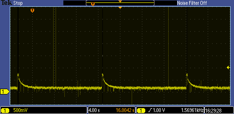
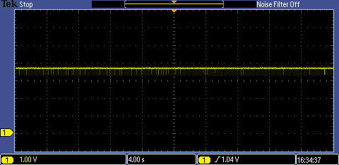
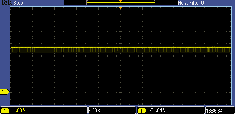
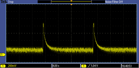
I am measuring a high on Vbat_ok when the battery voltage measures ~3.8V. For Vstor I am measuring 3.7V, Vref_samp measures ~20mA and then when the circuit is sampling it jumps to ~100mV.

It looks like the solar panel voltage when the MPPT is occurring is ~400mV but then it settles down to 80mV. I took the unit out in direct sunlight (cloudy day) and saw the solar panel voltage increase to ~800mV and settling back to ~350mA yet Vstor stayed at 3.7V.

What should I b checking to see why it doesn't seem that the battery is being charged?

Thanks,

George

  • Are you testing this on your own board? If you installed resistors>1Mohm, most of the new resistors using solder with flux, the residual flux can create parasitic, varying resistors in the 1Mohm range that are in parallel with your voltage setting resistors. The issue you are descibing looks like it is caused by the parasitic reisiance by the flux. You will need to clean the board thoroughly. If extreme cleaning with alcohol doesn't work for prototyping, try standing the resistors on their side (tombstone).

  • Yes, this is my own board and first bringup. I've read about the cleaning and have cleaned the board with IPA and inspected it but don't see any flux residue.
  • Have you tried with sanding the resistors on their side? Most of the times clean with IPA is not sufficient, it need special handling with a board cleaner that can remove ionic contaminants.
    When you standing the resistors on the side, you should see some improvement on the performance.
    If this does not work, please send the scopeshots probing VIN_DC, VSTOR, VBAT_OK, LBOOST in a scale like Figure 15 in the datasheet.
  • No we haven't tried standing the resistors on their side but we'll do that this afternoon and cross our fingers that this issue is indeed flux residue under the resistors.
  • Standing the resistors on their side did not change the measurements. I'm setting up for some scope plots but what scale is Figure 15 using? Are the gaps on LBOOST the MPPT measurement times at 16 second intervals?
  • Here are some scope plots. Let me know if this is not what you were expecting.

    LBOOST

    VSTOR

    VBAT_OK

    VIN_DC

  • I found something rather curious this morning. If I connect just the solar panel to the board and measure Vstor it is at the correct ~4.2V voltage but once I connect a battery to Vbat_sec the voltage drops to the same level as the battery. So with no load (or very little) the circuit seems to function as expected but once I attach a battery the system is not able to boost and create the charging voltage.

    • In parallel to Vbat_sec I have a 100uF cap
    • On the output of the ORing circuit (to select between Vstor and Vbat_pri) I have a 1uF
    • The output of the ORing circuit is connected to the input of a TPS63011 regulator which also has 10uF on the input
    • The output of the TPS63011 has 2 10uF in parallel
    • There is also a 100uF cap on the output of the TPS63011 placed at the input of my load. 

    The above test results are on a 2nd board we built which does not have the load circuit installed. If I try this on the board which is fully assembled I don't see the same results. Vstore only gets up to ~1V but that's not surprising because the solar cell is under 300mV and only under ideal conditions would this circuit be able to function from just the solar panel.

    So I'm a bit puzzled as to why the circuit appears to be functioning as expected (even with the solar cell output low) but once the secondary battery is attached the BQ25505 fails to boost the voltage and charge the battery. 

  • The IC monitors the voltage on VSTOR. Once VSTOR voltage rised above VBAT_UV, the fet connecting between VSTOR and VBAT_SEC closes shotting VSTOR and VBAT_SEC. This is why when the battery is connected to VBAT_SEC, VSTOR voltage drops to the battery voltage.
    Do you have a current probe that can measure the input current? Your first post mentioned the open circuit voltage of the solar panel is 1V and the current is 175mA. At what lux level does the panel produce 175 mA current? The input current limit of BQ25505 is 100mA, so the max charge current for the battery is 100mA. With a 870mAh battery, charging at 100mA and lower the charge time can be significant. More to that, considering I = Cdv/dt, the charge time dt = Cdv/I. Thus the time to charge up the battery increases with higher capacitance and lower current.
    When the system load is connected, and sufficient input power is not available, VSTOR does not get enough power to rise above VSTOR_CHGEN . It is highly
    recommended to add an external PFET between the system load and VSTOR. An inverted VBAT_OK signal provided by VB_SEC_ON can be used to drive the gate of this system-isolating, external PFET.
  • I have a few different small solar panels that I was going to try. The one that is connected doesn't have a lot of information available, the "data" can be found here.

    Unfortunately we don't have a current probe.

    I'm confused why you say that the max charge current limit is 100mA but the spec for I-CHG says 230mA typical and 285mA max. I realize that lower charging currents will take longer to charge a battery but if this is placed outside the available power will be more for a longer period and our thought was that using a larger battery would help provide power when longer periods of cloud cover occurred.

    It sounds like possibly if we place our sensor in sleep mode the circuit may work since Vstor would be able to rise since the load would be reduced. But my understanding based on the I-CHG spec was that 230mA would be available to charge and we need to double check but I think default current draw of our sensor is ~200mA.

    I read about using the external PFET but that assumes that you can completely power down your load and we wanted to always power our circuit.

  • The cycle by cycle current limit of the inductor is 230mA, which gives a average current of ~115mA. Therefore, the maximum input current limit is around 115mA.
    Please refer to datasheet page 18 equation 7, the larger the battery, the larger the equivalant capacitance of the battery will be. So using a larger battery will increase the overall capacitance.
    since your load circuit is drawing 200mA current, which exceeds the max current the part can deliver, you will not able to charge VSTOR up when the load is always connected.
  • Looking at that equation you get (2 x 850 x 3600) / 3.7 = a really large value! Sorry, but I guess what I'm missing in all of this is that I thought this would work sort of like a trickle charge. The system would pull it's load from the Li-Ion and the charger would add as much charge to the battery as it could. If I'm understanding what you're saying though it seems that this part will not work if your load is greater than what the solar panel can provide and then that is limited by 100mA. Effectively this is only good for applications that draw maybe 50-75mA max?

    I ran some other experiments which provided some interesting and unexpected results. On the board which has the load soldered down I pulled the enable pin low. I need to measure the current draw but the spec for standby mode is 0.9mA so I would expect if the part is disabled the current draw should be in this neighborhood. If I bring this board into the sunlight and only have the solar panel connected Vstor increases to 6.2V. On the other board without the load soldered down I get the correct value of 4.2V. I verified that the correct resistor values are placed (this is the board we rotated the resistors on their side to eliminate any possible flux residue). If all the settings are correct and the load is very low, what would cause Vstor to rise to 6.2V?
  • The bq255xx is designed for ultra low power system applications. It is essentially a boost converter that boosts low input voltage to a higher output voltage to charge up a storage element. The goal is to charge up VSTOR to VSTOR_CHGEN to enter main boost mode as fast as possible. When the VSTOR voltage rises to the VBAT_UV threshold, the PMOS switch between VSTOR and VBAT_SEC turns on, which provides additional loading on VSTOR and could result in the VSTOR voltage dropping below both the VBAT_UV threshold and the VSTOR_CHGEN voltage, especially if system loads on VSTOR or VBAT_SEC are active during this time. Therefore, we recommend to ust the PFET drive by VBAT_OK to disconnect the system load. Once the voltage on VSTOR rises above VBAT_OK, the PFET closess and the system load will then run by the battery if sufficiant input power is not availabe or the load current is higher than the part limit.
    The absolute maximum rating on VSTOR is 5.5V, so I dont see how VSTOR can rise to 6.2V without the part been damaged.
  • Maybe I'm dealing with a partially defective part then as I've ran this test several times and always measured 6.2V and I can see it ramp to this voltage. It's somewhat odd though since all the functions of the part seem to be somewhat working. I did confirm that when the load enable pin is pulled low the current draw is effectively 0 so this board that has the load soldered on should act just like the board without the load soldered (VSTOR only rises to 4.2V when no battery is connected on the "bare" board).

    You've mentioned a few times about using a PFET to disconnect the system load but I've mentioned that we don't want to do that. I can't see why someone would want to do that in any case as there are many options available if you can just "pull the plug" when you want to save power.

    What still bothers me is that it seems that you should be able to run your system off of the battery and then let the BQ25505 charge when it can.

    On page 20 of the spec I find "For example, if boost charger is configured to charge the storage element to 4.2 V and a 500 mA load transient of 50 μs duration infrequently occurs, ..." and then Figure 18 shows a test condition with a source meter set at 1A

    So I'm sorry but I feel like we're still disconnecting on some key points.

  • What you have quoted out is an calculation example of the additional capacitance needed to prevent VSTOR drooping when there is a load actived in a short period of time. This means the 500mA load is active only 50 us, and occurs infrequently. In order to maintain the voltage level on VSTOR, additional capaciance needed to be added.
    When you have your load connected and active all time, then there will not be enough power to charge up VSTOR.
    Figure 18 shows the sourcemeter setting int he experiment. When we set the current compliance to 1A which does not mean that the soucemeter is sinking 1A current. The IL (blue trace) shows the current goes through the inductor which is the cycle by cycle input current.
  • Today we're going to concentrate on the 2nd board that does not have the "load" soldered down. This is the board that does charge VSTOR to 4.2V when only a solar panel is attached. We're hoping that somehow the original board is defective and not working as expected.

    Of course our system will not draw a constant 200mA but it will need this current for when it is transmitting, hence the use of a Li-ion battery. (We currently have not programmed the module so by default it draws ~200mA when powered.) This makes perfect sense and everything in the documentation refers to this type of application. We chose a somewhat large Li-ion battery for our initial testing because we had planned to test for worst case and wanted to have plenty or reserve power. In our case there is more than enough "capacitance" so the VBAT_SEC voltage should never droop.

    What isn't clear, or at least to us, is that the BQ25505 will ONLY charge your battery when the load is LESS than the power available from the solar panel (or other energy harvesting source). This is further limited by the fact that you can only draw 100mA from the source or a maximum of 510mW. Is some of this energy still transferred to the Li-ion battery or does CSTOR act as a sink and is actually pulling power from the Li-ion.We never expected the solar panel to provide enough energy to power the system but we thought the BQ25505 would work like a trickle charger and provide as much power back to the battery as it could harvest.

  • If the load is connected to VSTOR then, when  the battery voltage is higher than VBAT_UV, the PFET between VSTOR and VBAT closes and connects the battery to VSTOR.  Your load and your battery are then both connected to the output of the boost converter (VSTOR).  If your load pulls more current than the boost converter can output, all of its output current will go to the load and the battery will supplement the rest of the load current needed.  When the load current is less than the boost converter output, then the battery will get charged by the difference.  Kirchoff's Law:  Istor + Ibat + Iload = 0.   Keep in mind the boost converter output current will be much less than its input current.  You can estimate the boost converter output current (ISTOR) using a power balance where efficiency = Pout/Pin = VSTOR*ISTOR / (VMPP*IINAVG).  Efficiency can be estimated from the datasheet efficiency curves and IINAVG is 100mA max (200mA peak typical) assuming your panel has ISC>=200mA and you are in full sun.

  • Hi Jeff,

    Thanks for jumping in and clarifying this. I figured the energy that was harvested had to go somewhere but it just wasn't clear before if that energy when into the system load somehow.

    So in our case when we want to pull as much energy as possible is it best to have a panel that also has a high Voc, as long as it's below 5V or do we need to keep the panel voltage below Vbat_ov? I wasn't sure if the MPPT circuit would sense the higher voltage and adjust to bring it down. If you can't tell this is my first solar powered project.

    We did just run a quick check on the 2nd board and jumpered in the load circuit. I confirmed that when the circuit is disabled VSTOR only rises to 4.2V and doesn't go to 6.2V like the original board. I guess the BQ25505 got slightly damaged on our 1st board and has been causing us some additional confusion. Other than VSTOR rising to 6.2V all other functions "seem" to be operating properly which is odd though (yes, we've triple check the resistor values and that they are mounted correctly).

    I know now that the BQ25505 isn't the best part for our application but there really isn't another part that does this so I believe it's our only choice. Can you think of some options to improve this circuit for applications like this?

    Thanks,
    George
  • VMPP setting needs to be less than VBAT_OV setting or the IC will turn on a pull down FET at VIN_DC. Other than resistor problems that Jing has already discussed with you, the only time we have seen the IC not regulate properly was due to switching noise into the VSTOR pin causing the part to think it is in unregulated cold start. You can confirm if this is the problem by looking at the VRDIV node. To prevent this you need to have a 0.1uF or 0.01uF capacitor as close as possible between VSTOR and one of the IC GND or NC pins.
  • We have VOC_SAMP tied directly to VSTOR so VMPP=80% so based on that I assume a panel with Voc up to 5V would be OK? I'mjust trying to determine what the best panel specs would be to squeeze as much power from the panel as we can. We're talking about relatively small panels so +/- a few cm isn't a big deal.

    We do have a 0.1uF bypass cap (C5) close to VSTOR, as well as a 4.7uF (C4). See the attached top side layout view for reference.

    BTW, I was discussing the cleaning requirements with my CM and after a little research we both believe that trying to achieve >50M ohm DI resistivity is not only quite hard but extremely rare in the industry. I read in the notes that decreasing your resistors by a factor of 5 is recommended so if Rsum was reduced to 3M (from 13M) is the only drawback increased current consumption? We're just fearful that if we get this into production we might run into some issues since this seems to be a critical point in the design.