This thread has been locked.

If you have a related question, please click the "Ask a related question" button in the top right corner. The newly created question will be automatically linked to this question.

TPS65217 power down

Other Parts Discussed in Thread: TPS65217

Hello,

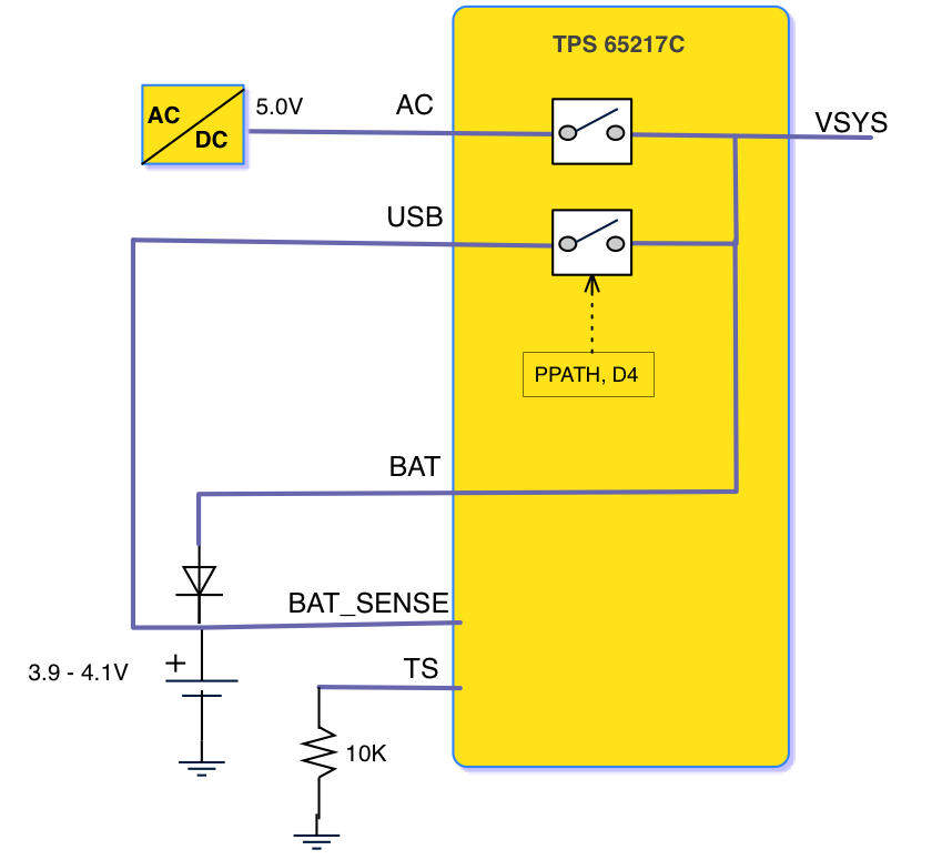
I'm investigating an issue when using a TPS65217 to feed a Sitara processor, with no battery backup. This issue is present in the Beaglebone Black board and is the possible cause for hundreds of board failures.

The problem I found is that the power down sequence is not completed, even when using the SW shutdown and keeping the 5V input enabled. The situation is worse when the 5V input is suddenly removed, without calling the SW shut-down first.

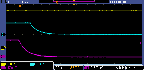
By probing all the power rails I found this: As soon as the shut-down sequence is started, the SYS output is shut-down so all the regulators in the PMIC lose their power source. Only the energy stored in the capacitors at the SYS rail is what feeds the whole power down sequence. This is the case even with a SW shutdown.

In the case of the BBB, there is a significant amount of capacitance (around 150uF), but this is not enough (it's close) to complete the shut-down sequence when powering down by software.

With the sudden removal of the 5V, the available energy is pretty much one half because the shut down sequence is started by the UVPLO event, which (for some reason) has a threshold of 3.5V (3.3V + 200mV typ). When the SYS caps have 3.5V, their energy is 1/2 as compared to 5V.

My questions are the following:

1) is this IC supposed to use the energy stored in the SYS pin caps to complete the shut-down sequence? maybe I missed it in the datasheet, but I haven't seen it. And probably the BBB designers didn't see it either.

2) so far, the solution I found to make the BBB (and my custom board) be able to complete the power-down sequence (even with a sudden shut down) is to increase the SYS capacitance by 300uF or more. This capacitance depends on what circuits are fed by the PMIC. Is there any other way to address this issue?

3) is there any way to increase the threshold of the UVPLO so the energy usage in the caps is more efficient.

4) please confirm me that this PMIC was designed to handle a sudden 5V shutdown (removing the 5V input) without calling the SW shutdown command before. This is with no battery backup.

Thanks for your help,

Max

    1. is this IC supposed to use the energy stored in the SYS pin caps to complete the shut-down sequence? maybe I missed it in the datasheet, but I haven't seen it. And probably the BBB designers didn't see it either.

    No, the System pin should be maintained during and after the power down sequence. I used the TPS65217C EVM to confirm this. On this device the DCDC3 (CH. 3) is assigned to strobe 5, the last rail controlled by the sequencer to be enabled, and DCDC1 (CH. 2) is assigned to strobe 1, the first rail to be enabled by the sequencer.  Using our GUI I set the SEQDWN bit, is this  what you meant by software shut down? When I set this bit DCDC3 shutdown first DCDC1 shut down last, the reverse of the power up sequence; see picture below.  


    2.   so far, the solution I found to make the BBB (and my custom board) be able to complete the power-down sequence (even with a sudden shut down) is to increase the SYS capacitance by 300uF or more. This capacitance depends on what circuits are fed by the PMIC. Is there any other way to address this issue?

    Let me look into this once I get the BBB board modified.


    3. is there any way to increase the threshold of the UVPLO so the energy usage in the caps is more efficient.


    The threshold is set by the UVLO, which is programmable, and the Voffset, which is fixed; giving you a range from 3.5(UVLO set to 3.3)  to 2.9 (UVLO set to 2.7). There is no other way to increase or decrease beyond these thresholds.

    4) please confirm me that this PMIC was designed to handle a sudden 5V shutdown (removing the 5V input) without calling the SW shutdown command before. This is with no battery backup.


    Yes, this device was designed to handle a sudden 5V shutdown (without back up battery). I repeated the same experiment, but instead of setting the SEQDWN bit I just removed the 5V AC power input, this triggered the power down sequence as seen below.

    I am unable to reproduce what you are seeing with our EVM, let me get a BBB board modified so I can probe the board and correlate my findings with yours; would you please provide your screen shots, illustrating this issue?


    Janice

  • Hello Janice,

    Thanks for your response.

    First of all, let me clarify that the device I'm using is a TPS65217C, the one in the BBB. Here is the schematic for your reference:

    github.com/.../BBB_SCH.pdf

    I call "SW shut-down" the command from linux "shutdown now –h", which is supposed to be the "best" shut-down possible. I believe that it uses the PMIC_POWR_EN signal (see BBB schematic) instead of directly the SEQDWN bit.

    What you see in the EVM is not what I see in my captures with the BBB. It may be the method for shutting down, but probably the main difference may be in how loaded the SYS_5V supply is. The BBB feeds some ICs from this rail, your EVM may have nothing connected to it (I see that the decay speed is pretty slow).

    In my capture, the 5V output by SYS are clearly shut down at the moment the PGOOD signal goes down, the caps start to get discharged at that moment.

    Here is a capture with a SW shut-down command that shows how the 5V starts to go down together with the PGOOD signal. VDDS_DDR t loses regulation before shutting down, and it actually shuts down 1.5ms before it should. I'm using BBB_SCH netnames to be 100% consistent.

    ch1 = PMIC_PGOOD (after U16)

    ch2 = VDDS_DDR

    ch3 = SYS_5V

    ch4 = VDD_CORE

    We added a 220uF cap to SYS_5V that increases the stored energy by more than 100%. Now VDDS_DDR is able to shut down at the right time (10ms after PGOOD goes down). This is still with a SW shut down:

    Something similar happens with the sudden shut-down, but unfortunately the 3.3V outputs are not able to stay regulated because the UVP level is too low (3.5V). This may not be a very critical issue because losing the 3.3V regulation "shouldn't" damage the uP.

    Here you can see the same signals, with 220uF extra cap and with a sudden removal of the 5V instead of the SW shutdown.

    My main question at this point is: In a sudden shut-down event, how is the PMIC supposed to feed the regulators for the 10ms that the turn-off sequence lasts? I don't see any other way than having a good amount of capacitance to store energy. The 2 issues I see are:

    1) The low UVP threshold (3.5V) is a big problem because it pretty much guarantees that the 3.3V regulation will be lost right away (unless there is infinite capacitance).

    2) The other issue I see with the IC is that the only place to store energy is at SYS_5V, which is used to feed the PMIC regulators and also the "system load" (per datasheet), so any external loading at this pin will affect the capability to achieve the power-down sequence in a sudden 5V removal.

    My other question is: do you see possible any workaround or trick to use the battery pins to be able to make the UVP trigger at a higher level? that would help a lot fix this issue.

    Thanks for your support,

    Max

  • As soon as the TPS65217 begins a power-off sequence, regardless of whether this is by software request (PWR_EN going low with the OFF-bit set) or due to fault or pmic reset, the power path is disabled and SYS is connected to BAT. If no battery is present, it will indeed be running solely on whatever capacitance SYS has.

    Note that on a BeagleBone Black rev A6 or later this is actually a good thing since the 3V3B regulator fails to shut down as long as SYS is supplied, and I've seen scary things on the scope when SYS remains supplied (via BAT) at 3.6V.

    Given that VDDS also seems to leak heavily to VDDHV during shutdown, I'm wondering whether it wouldn't actually be better to set the INSTDWN bit in SEQ6, or at least program a much shorter shutdown sequence.

  • Matthijs,

    I just saw your previous posts and I wasn't aware of the the 3V3B regulator issue. I agree that 3V3A is not the best signal to enable/disable the regulator. What fix did you end up using?

    Using PGOOD seems to be the simplest, but it would significantly change the timing of 3V3B signal. In the power-down sequence it would it turn-off before VDD_CORE and VDD_MPU, which may not cause any problem. Do you have any concern with that?

    In your other post you mentioned the idea of making 3V3B track the voltage of 3V3A, what type of IC would you use? some type of linear amplifier would be required or a voltage follower made with a transistor.

    My opinion regarding making changes by SW in the sequence or power-down method is that I wouldn't consider it to be 100% reliable. There can be situations where the SW doesn't have enough time to configure the PMIC before the power goes away. That would leave the PMIC with its default setting.

    Regards,

    Max

    PS: are you investigating the BBB PMIC issues because of HW failures or because power consumption?

  • Maximiliano Sonnaillon said:
    I agree that 3V3A is not the best signal to enable/disable the regulator.

    It's not even really a signal at all. It's a supply line. A digital signal is supposed to cleanly transition between logic-low and logic-high, and 3V3A's falling edge most certainly does not qualify. And of all supply lines to abuse for the purpose, it was quite probably the worst possible choice. 

    Using PGOOD seems to be the simplest but it would significantly change the timing of 3V3B signal

    As far as I can tell PGOOD would be the best choice of enable-signal, certainly for shutdown: it gives the 3V3B as much time as possible to discharge on its own before the 3V3A is severed, and at the same time PGOOD going low asserts the power-on reset signal of the processor, which causes all its I/Os to go high-Z (with weak pulls) thus preventing any serious leakage in the opposite direction.

    The only thing to be careful about is that shortly after power-on reset is released (PGOOD goes high) the SYSBOOT pins (lcd data 0-15) are sampled. If these pins are used as inputs in your application, external hardware must refrain from driving them to undesirable values until the processor is released from reset. If the pins are used as outputs (e.g. for HDMI or LCD) then there's no concern.

    Update: a problem has surfaced: PGOOD is a 1.8V signal while the 3V3B-regulator specifies ≥ 2V for logic-high. Inconvenient.

    In the power-down sequence it would it turn-off before VDD_CORE and VDD_MPU, which may not cause any problem. Do you have any concern with that?

    None whatsoever.

    The only thing that matters is that the AM335x IOs become high-Z (with optional weak pull-up/down) before or at the same time 3v3b power is cut, and this happens as soon as PORz goes low (asynchronously afaik).

    In your other post you mentioned the idea of making 3V3B track the voltage of 3V3A, what type of IC would you use? some type of linear amplifier would be required or a voltage follower made with a transistor.

    Although they're not as common, voltage-tracking LDOs do exist (e.g. the TPS7B4250-Q1).

     What fix did you end up using?

    This exceptionally-low-dropout regulator ;-)

    In general using the same power rail for an IO bank supply and the external hardware connected to it is the surest way to avoid problems. Partitioning the current can sometimes be done along the boundaries between different VDDHV supplies.

  • My opinion regarding making changes by SW in the sequence or power-down method is that I wouldn't consider it to be 100% reliable. There can be situations where the SW doesn't have enough time to configure the PMIC before the power goes away. That would leave the PMIC with its default setting.

    True, but such cases would probably be very rare, so if helps to avoid undesirable current paths or otherwise improve the long-term health of the processor it would still be worthwhile.

    Of course this is hard to evaluate.

    PS: are you investigating the BBB PMIC issues because of HW failures or because power consumption?

    I've not yet seen any HW failure. Even the BBB which has been the subject of most of these electrical tests seems to have survived intact, although its UART0_RXD pin probably hates me now (yet still performs its duties without complaint).

    It actually started with some investigation on how to hook up a Li-ion battery to give us time to perform a clean shutdown when power is disconnected (to avoid eMMC corruption), and I gradually stumbled over various oddities, so then I quickly reached the point of wanting to know exactly what's going on with the PMIC and power management in general on the BBB.

  • Hey Guys,

    The problem of using a LiIon battery to allow BeageBone boards to orderly shutdown is object of several posts here.

    In my particular case I just want to use the battery power to allow shutdown and disconnect the battery from the power path at the end of power down sequence to work around the problem of VSYS being kept with 4,1 V causing VDD_3V3A to set to around 0,8V.

    As I don't intend to run on battery nor on USB, I came up with this solution and I would like to have your thoughts in why it didn't work ....

    The whole idea is to connect the battery in the USB input of the PMIC (instead of BAT terminal) allowing battery power to be connected/disconnected using power path control bit D4 in the Power Path Control Register (PPATH). With this I can change the shutdown routine of the OS to disconnect the battery power from VSYS just at the end of the power off cycle, before issuing the POWER_EN Signal.

    As the battery still needs to be charged, my idea is to connect BAT SENSE to the battery (+) and connect BAT to BAT SENSE via a low Vf diode in order to prevent the battery from supplying the original power path. It should work because the charging cycle tests the battery presence sending a small current to it and sensing the voltage (via BAT SENSE I suppose). Naturally TS is supposed to be connect do a 10K resistor to ground.

    However, it didn't work! PMIC just didn't turn on when AC input is connect to a suitable 5V power supply.

    Does someone can explain why not?

    Best regards

  • Hi Angelo, thank you for the post. I have assigned the engineer supporting this device to respond. This appears to be the same question asked on a new separate thread, is that a correct assumption? Best Regards, Scott
  • YScott, Yes. Sorry for duplicating. I'm a newbie in this forum.
    regards
  • Angelo,

    I will answer the other Thread (e2e.ti.com/.../2272252) because it is independent of this question and may not have the same solution.