This thread has been locked.

If you have a related question, please click the "Ask a related question" button in the top right corner. The newly created question will be automatically linked to this question.

pwm freq is not correct in the UCD9222

Other Parts Discussed in Thread: UCD9222, UCD7242

Hi all;

I am working on the UCD9222 device with two UCD7242 to output two voltage rails(Cvdd and 1v0). Generally speaking, it work ok except the pwm freq is not the same as the one set in the configure file(xml file).

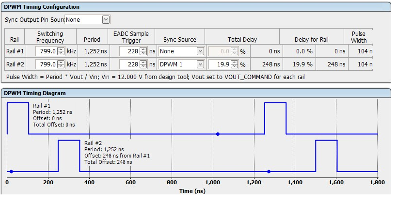
In the xml file, two rails set pwm freq for 670Khz. 

but measure from the oscilloscope, it is only about 593khz.

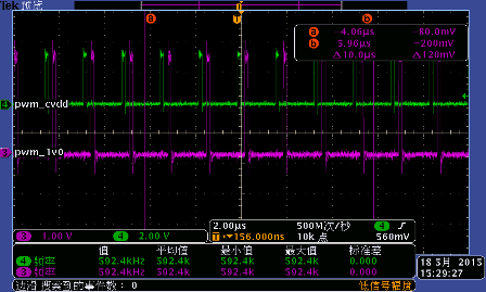
Question: why the pwm freq is not the same as the one set in the configure file? About factor will impact this case?

Attached the schematic and xml file.cs_xml_file.rar

  • Hi Stonenut,

    The PWM frequency should not deviate more than +-5%.  

    Please check if other parts have the same problem. If necessary, please contact local sales for failure analysis.

    Thanks,

    Zhiyuan

  • Hi zhiyuan and all;
    Actually, we use the same circuit(UCD9222 and 7242) in two products. Let me called them A and B. The schematic and configure file(xml file) are the same except the PCB trace betweem A and B.
    The pwm freq issue only appear in the product B(all B have this issue), but A's pwm freq is ok as it define in the xml file.
    I do a test to exchange the UCD9222 part between A and B. It is surprised that the pwm freq issue still appear in the product B after the UCD9222 exchanged. However, the pwm freq is still ok in product A after the exchanged job.
    In a word, it seems that it is not the UCD9222 part issue and this issue only appear in the product B. and something difference(different PCB trace) between A and B bring this impact. Any good suggestion to fix this case?
    Thank you!
  • Is there a PMBus host on the board that may have changed the switching frequency after the project file is downloaded?

    I suggest save a project file for each of the A and B board after the problem happened, then use Fusion GUI to compare the differences of the two project files. The  Device/Project Configuration Compare Tool is under Tools menu.

    Thanks,

    Zhiyuan

  • Hi zhiyuan;
    Thank you for your quick response.
    there is no PMbus host on the board. we only use the TI usb to GPIO(SAA) tool to download the configure file and after that there is no any other host will connect on the PMbus for UCD9222.
    A and B use this same UCD9222 configure file.but anyway I will do a test to compare the A and B xml file to see whether there is something different in tomorrow.
    Thank you!

    stonenut
  • Hi zhiyuan;

    The compare for A and B 's xml as enclosed.

    pls. note that in the compare file, the UCD9222@78[1] belong to product A , and UCD9222@78[2] is product B.

    it seems they are almost the same.


    any good suggestion for this case?Device Configuration Comparison.pdf

    stonenut

  • Hi Stonenut,

    The configurations are indeed the same. Can you measure the input current to the device on both boards? If you slightly change the switching frequency configuration, will the device on B board change accordingly?

    What is the text marked on the package? It should have 3 rows as below:
    UCD9222
    TI xxx
    xxxx xx

    Thanks,
    Zhiyuan
  • Hi zhiyuan;

    (1)the switching freq can change base on the new pwm freq config in xml file.

    I set switching freq= 799khz,but it only output about 670khz freq.

    see below for detail:

    the new freq get from the oscilloscope:


    (2)both the product A and B use the same IC batch.

    the IC marked as below:

    UCD9222
    TI 28K
    CGN7 G4

    By the way,I ever exchange the UCD9222 between product A and B(remove A's UCD9222 and solder it to B etc..). this issue still happen in product B and A is alaway ok.

    (3) I do not measure the input current for both boards due to no current probe in hand now. what do you want to get from the input current? you want to check the inrush?


    Thank you!

    stonenut

  • Hi Stonenut,

    I wanted to know if the UCD9222 devices, while on different boards, have the same current consumption, or have the same voltage on V33D/V33A, BPCAP, or same conditions on other pins. We need to find out the differences of the two operating conditions, and then analyze what could be the cause of the problem.

    Thanks,

    Zhiyuan

  • Hi zhiyuan;

    The V33D/V33A is the same for both A and B product. and the voltage for Bpcap pin is almost the same.(A is about 1.75V and B is 1.68V).

    By the way, we found the the B product have a issue to power up under the 0  deg C.(B have the pwm freq issue and A is ok to work under -20 deg C). 

    is there any relation between the pwm issue and low temp power up?

    stonenut


  • BPCAP is 1.8V nominal. 1.68V seems too low. If the same device's BPCAP is 1.75V on A board and changed to 1.68V on B board ... it shouldn't be. Is there any circuit loading the BPCAP? (BPCAP should not be loaded) Is BPCAP properly decoupled? (tie 0.1 - 1μF cap to analog ground)

    Do all B product boards have this problem or just a few devices have this problem?

    Thanks,
    Zhiyuan
  • What is the PMBus address of the device on B board? If the address is 126d, JTAG is enabled and the clock will be slowed down. So make sure the address is not 126d.

    The BPCAP=1.68V is too low. It is 1.8V nominal. The lowest that can pass our ATE test is 1.69V. Make sure no external circuit is loading it.

    I've checked the lot trace code you provided. The device you have is from the old silicon version. You can ask for samples of the new silicon version devices and see if the problem is solved.

    Thanks,
    Zhiyuan
  • Hi Zhiyuan;

    The PMbus is 78d for both product A and B.you can reference the cs in below link: e2e.ti.com/.../cs_5F00_xml_5F00_file.rar

    For the Bpcap/V33 voltage, here is some test data in below: B_#1: Bpcap=1.683; V33D/V33A=3.287; B_#2: Bpcap=1.694; V33D/V33A=3.276; B_#3: Bpcap=1.752; V33D/V33A=3.266; A_#1: Bpcap=1.752; V33D/V33A=3.280; A_#2: Bpcap=1.755; V33D/V33A=3.288;

    it seems that the voltage of Bpcap in B is a little smaller than A's.

    BTW. an interesting finding for the PWM freq. When remove both the  UCD7242 in the PCB, B's UCD9222 can output the freq what we wanted. As no UCD7242 in the circuit now, the duty for this PWM is not correct but it is ok for the PWM freq. see below for detail.

    we retest it in the product A(also remove both UCD7242), but the PWM freq is still ok.

    it seems that the UCD7242 in product B bring impact to the UCD9222's PWM freq output. Amazing!!

    stonenut

  • I'm guessing the noise introduced by power stage affected the clock frequency and it may be related to layout. Have you checked whether the BPCap PIN voltage is clean?

    One test you may try is to use the UCD9222 on B board to control the power stage on A board. This will isolate the noise and see if UCD9222 on B board can function correctly without noise.

    You may also improve decoupling cap locations (or grounding) on BPCap and V33D and see if there is any improvement.

    Thanks,
    Zhiyuan
  • Hi Zhiyuan;

    I need some days to test again base on your suggestion as I am busying for other case.

    I am a little surprised that the pwm freq for 9222 have some relation with the PCB layout, as there is no document show this notication to us.

    A and B boards use the same circuit and both are base on the demo board design.

    stonenut