Hi,
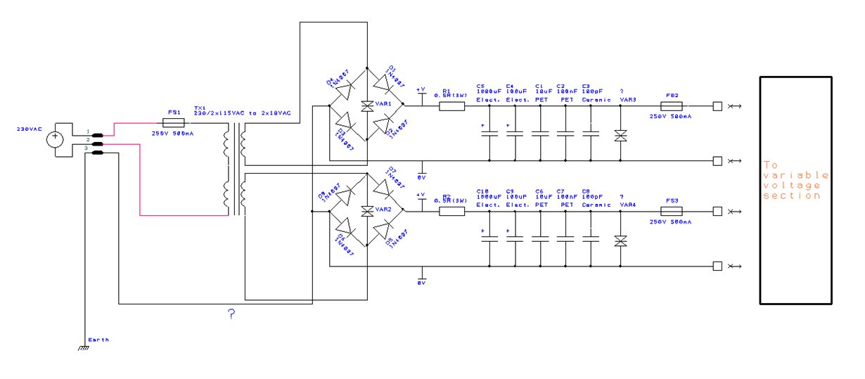
I'm halfway through making a simple dual power supply for home use (5.5 - 15.5VDC; approx. hopefully 0.75A max. but probably only 0.5A at most to avoid frying a TO220 linear regulator suffering 24VDC down to 5VDC), and wanted to know if the connection between the DC 0V output from the rectifier to the earth line on a single phase domestic mains line (230VAC) is actually a safe way of grounding the circuit, or if it is a dodgy practice I found on the Internet. I copied this idea from a web which goes into detail on AC/DC power supply design, and the information and depth of design seemed sensible and legitimate, but as this is the first time I am trying to put together a decent power supply, I have some doubts as to whether this is a sensible way of doing things: for example, I imagine that it is inadvisable to connect the power supply box chassis to the same ground/earth point with this configuration. I saw in another sensible webpage pdf quite detailed advice and diagrams about grounding DC circuits to Earth with only one ground point to avoid current loops. In short, reading is safe, but doing can accidentally be dangerous, especially with incorrect or misinterpreted information.
I have the basic power supply up and running (as these things can't go on breadboards) - identical to the schematic, and in principle for short periods of time while I've been experimenting with R values for the variable voltages it seems fine (no excessive heat yet), I still need to solder/add the variable voltage part of the circuit when some 7W resistors arrive and change the electrolytic 25VDC caps to 63VDC, and hope to implement a PMOS bleeder and a soft start circuit, if I can get them to function correctly.
a) Is it better to leave the DC 0V supply lines isolated from the AC Earth connection but connect the box chassis to the AC Earth connection?
or b) Is it okay/good practice to connect the DC 0V supply lines and the metallic box chassis to the AC Earth connection?
or c) None of the above?
If anyone has a sensible/safe answer, I'd really appreciate the input, as I want to make a safe power supply, not a ground looping taser!
Thanks.
Attached is a schematic of the circuit so far, please ignore VAR3 and VAR 4 as they are space fillers where the bleeder PMOS + 1K 7W R will go:


