This thread has been locked.

If you have a related question, please click the "Ask a related question" button in the top right corner. The newly created question will be automatically linked to this question.

TPS92641 doesn't stabilize VCC

Other Parts Discussed in Thread: TPS92641

Hi,

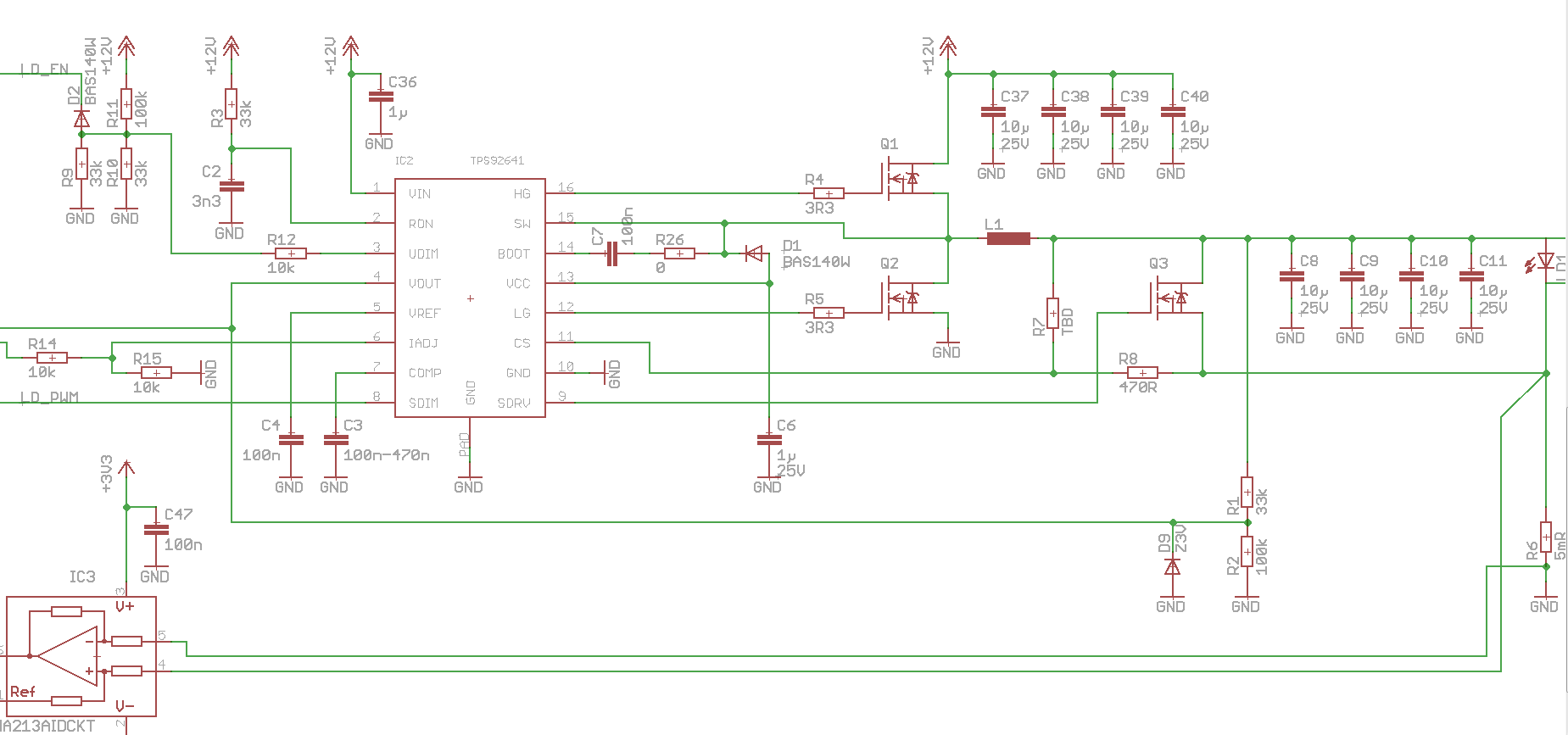
I'm trying to use the TPS92641 in led driver application. Unfortunately, my first prototype wont work properly. I tried to do the schematic and layout like in the EVU board, but with supply voltage of 12V and one single power LED as load.

The problem is the integrated 8.5V voltage regulator wont work properly. The voltage on the VCC pin is a sawtooth oscilation around 5V with 1V pk-pk and about 20kHz. This seems to be the VCC-UVLO point. Also The Ron pin is oscillating at the same frequency. The Vref voltage (not needed in my design) doesn't achieve 3V.

I tried several combinations of Ron/Con and several different COMP/VREF/VCC decoupling capacitors. The oscillating frequency is changing slightly, but the regulator wont start working. When I turn the supply voltage below UDIM UVLO threshold (UDIM<1.276V), the regulator doesn't oscillate.

The shunt FET for SDIM is not populated yet.

Thank you for your help.

P.S.: This design http://www.ti.com/lit/an/snva725/snva725.pdf 

  • Forum ate my text after the PDF-link. My Question was: the guys in that design (DLP nano) use 2.2nF caps on COMP pin, but the datasheet says, use 100nF-470nF for compensation. Ist there a reason for such small value?
  • Sorry, but you might have to bear with me a little. The person who knows this device the best is out for 12 weeks. But I did look it over and see some things that might concern me and could cause problems. The first is that I calculate you are using a switching frequency of about 12.2kHz. Is there a reason it is set so low? I don't believe this part was designed for that low of a frequency. Not only are you likely to hit current limit each cycle (depending on your inductor value) but the switching frequency itself may be interfering with the control loop at this point (you generally want a crossover frequency of 1/6th the switching frequency maximum). The second if that the output OVP level is set to just above 4V. This might be ok depending on your LED, but usually you want some extra headroom so that if the output voltage overshoots at startup due to fast charging caps you will not accidentally trip OVP. I would start by adjusting the OVP (if needed) and then increasing the switching frequency significantly (after changing OVP resistor values since that is part of the equation).
    As for the comp cap, the datasheet suggestions are there to make designing easy and generally provide plenty of bandwidth for most applications. I don't know who did the DLP design or why they used 2.2nF, but perhaps they needed more bandwidth. You can use lower values, but at some point you need to start taking into account other system poles/zeros to make sure you have enough phase margin.
  • Dear Clinton Jensen, Thank you very much for your hint about the switching frequency. I changed it.

    But the problem was the wrong bootstrap circuit (esp. the diode connection). Now I fixed the layout and the IC works very well.