This thread has been locked.

If you have a related question, please click the "Ask a related question" button in the top right corner. The newly created question will be automatically linked to this question.

TPS23751 force work in PWM mode without load

Other Parts Discussed in Thread: TPS23751

Hi,

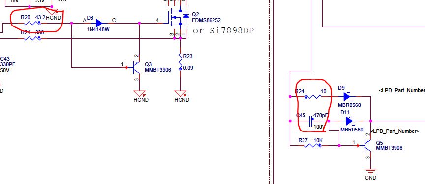
We design an 12V poe output with TPS23751. Since the load is always heavy so we force it to PWM mode by connecting SRT pin to GND(Manually change current SCH). But when we don't connect the load  we find the secondary FET also gets very hot(70 C). When we change back to VFO/PWM auto mode, the secondary FET is very cool since it doesn't need work. So our question: Is it a normal situaltion for secondary FET becoming very hot when force work in PWM mode while light load.  Is it caused by efficiency lost? Are there any parameter change to decrease the temperature?

Attachment is our sch.poe_12v1.pdf

Regards,

  • Q4 is most likely getting hot due to switch overlap with Q2. You might have to "tune" primary and secondary side switching to add some delay to prevent conduction overlap by adjusting the gate drive phasing components.


    Self driven (secondary side FET driven by the transformer, U5) designs operating at 12V output are more difficult to tune because the secondary side FET must have a higher voltage and with that has higher gate charge.

  • Thank you Eric,
    Do you have any detailed guide or best waveform description for good primary and secondary switching phase?
    Do you mean that the tempareture will go down when the efficiency go up?
  • Thank you! Eric,After changing the C45 from 470pF to 6.8nF, the efficiency increased 4 percent and Q4 temperature decreased a lot. Change R20 and R24 have no good result. 

    Another question: What's the equation between load Iout and VCTL, I want to change the Vsrt according to the load Iout value. Then I can change the VFO/PWM threshold to meet my load value.

  • Hi Lonsn,
    Unfortunately there is no specifc equation in the datasheet. The best soltuion is to follow the assumptions on page 31 of the datasheet. The component connections will already be there. Then, from bench testing, you can easily find your desired 'sweet spot' for PWM/VFO transition by slightly varying VSRT with one of the resistors of the resistor divider.