This thread has been locked.

If you have a related question, please click the "Ask a related question" button in the top right corner. The newly created question will be automatically linked to this question.

BQ24133 - Alternate parts for MOSFETs in BQ24133EVM Design

Other Parts Discussed in Thread: BQ24133, CSD25310Q2

I've taken the circuit from the BQ24133EVM board and laid it out on a PCB, but we're having trouble getting the battery to charge.  When we plug in the power supply, the status LED blinks and the battery voltage stays at around 7 V even though the ACDRV and BATDRV signals go high to select the power supply.  We subbed in different parts for the MOSFETs in the design.  Can you verify that the following parts will work in the design?

Q1:  NXP BSS138P,215

Q2, Q3:  Vishay Siliconix SISA10DN-T1-GE3

Q4:  Vishay Siliconix SI2323CDS-T1-GE3

Steve Trani

  • Hi Steve, 

    The blinking STAT pin indicates that there is a fault condition.  If you would please provide a schematic and any relevant scope capture you have for VIN (plugin), SW, BATDRV, and ACDRV I'm happy to help you troubleshoot the issue. 

    Thanks!

    Rachel 

  • Rachel,

    Attached is a pdf of the schematic.  I'll work on getting some scope shots.

    Steve

    110367 Inno Optics Battery Board Schematic Rev 2 A.pdf

  • Steve,

    Nothing about the schematic is jumping out at me as incorrect. Maybe the scope shots will shed more light on the possible fault. 

    Thanks,

    Rachel

  • Rachel,

    Do the MOSFETs look correct? Are the parts valid subs?
    When \BATDRV is low, VBAT should be switched on to PVCC, right?
    And when ACDRV is high, +12V is switched on to PVCC?

    Steve
  • Rachel,

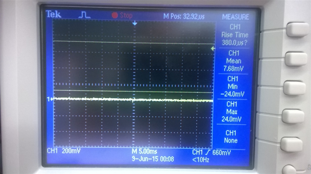
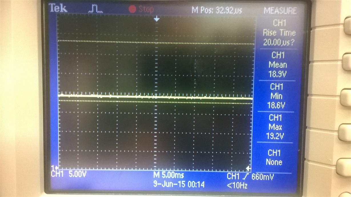
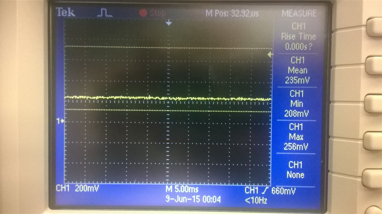
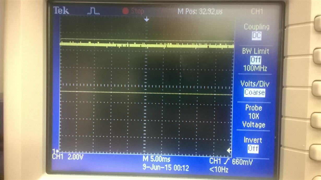
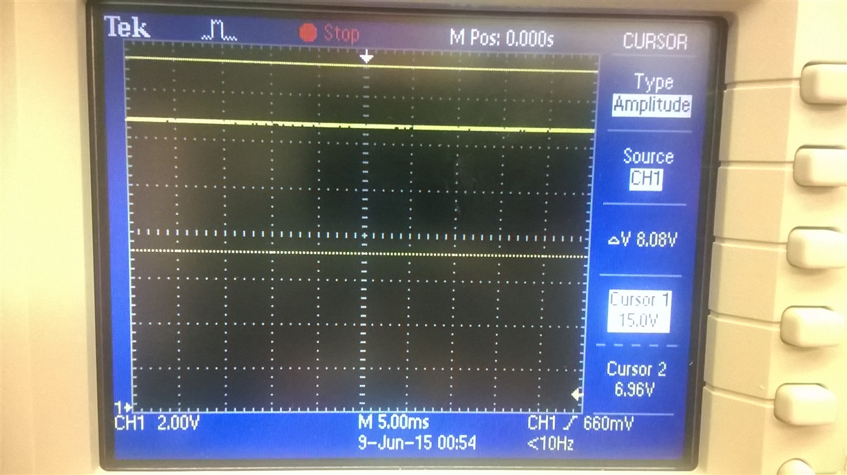
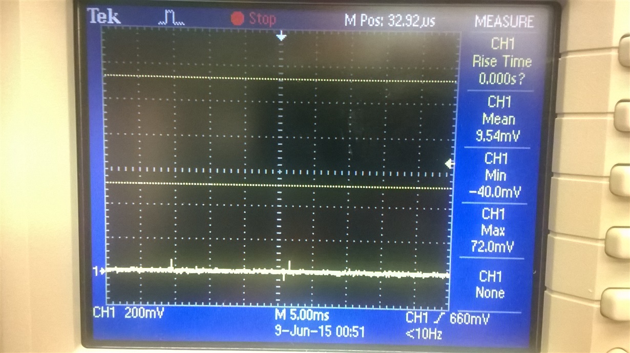
    Here are scope shots of VIN, \BATDRV and ACDRV with the power supply connected and disconnected.

    Steve

  • Here's an update: we measured the resistance from ACDRV to CMSRC and saw 335K. That resistance has to be over 500K, right? We pulled the reverse protection transistor and resistor (Q3 and R10) and the resistance jumped up over 500K, but the BQ24133 is still in fault mode. Should we try different N-channel MOSFETs?
  • Rachel,

    We changed the N-channel MOSFETs to the same one used on the evaluation board and there was no change in behavior of the circuit. We also changed the P-channel MOSFET to a T.I. CSD25310Q2, which is supposed to be a good sub for the P-channel MOSFET used on the evaluation board. No difference. Any ideas on what we should try next? We're running out of ideas.

    Steve Trani
  • Steve,

    Sorry I haven't gotten back to you sooner, but thank you very much for your timely updates.  Since STAT is blinking we're going to need to go through the possible fault causes and eliminate them. 

    Here is a basic overview of possible faults:

    • Timer Faults
      • Fast Charge Timer(TTC) expires: Pull TTC HIGH to disable timer for debug
    • TS fault
      • If TS pin is outside of safe charging threshold - charge is suspended and STAT blinks.  What voltage is TS?
    • Short Circuit Protection
      • Cycle-by-cycle current monitoring feature achieved by monitoring the voltage drop across Rdson of the MOSFETs.  Charger will latch off and STAT pin will report fault condition. can be reset by removing and re-plugging the adaptor 
    • Input Over-voltage
      • OVPSET rising > 1.6V typ.  You have all the recommended circuitry to prevent false triggers, and the ACDRV is turning on so I think this is fine.
    • Battery over-voltage
      • VBAT > 104% of regulation voltage.  If over-voltage persists longer than 30ms, charge is disabled, you have measured VBAT =7V and CELL=Float(8.4V) so I think we're good here
    • Battery Absent
      • See figure 18 on page 20 for battery absent conditions

    For debug purpose, is it possible for you to remove BATFET (no system power) just to see if the part will work as a pure charger without the powerpath selector?

    Thanks,

    Rachel 

  • Rachel,

         We connected TTC to VREF.  Is that what you meant by pulling it high?  In any case, STAT kept blinking.

         TS is at 1.88V.  That's okay isn't it?

         Where on the MOSFETs do we measure the Rdson voltage?  Is it from drain to source?

         For the battery absent conditions, do you mean figure 14 on page 20?

         We can remove BATFET.  Do we need to short across the drain and source pads of the BATFET component site?

    Steve

  • Rachel,

    I understand how BATFET works. We didn't short across the drain and source, but removing the MOSFET didn't change anything. We're still not seeing 8.4V at the battery.

    Steve
  • Steve, 

    Sorry I'm not clear, is the STAT pin is still blinking?  If so, you need to look through all the possible fault conditions and eliminate them as the source before we can consider any other issues. Not seeing 8.4 on BAT doesn't necessarily mean the IC isn't working. 

    • TTC is pulled high to VREF - OK
    • TS is 1.88V which is 56% of VREF - OK

    Other set-ups to try:

    • With an appropriate battery voltage (i.e ~7.4), can you measure a charge current? You can do this by measuring the voltage across the sense resistor.  
    • If you remove the battery can you use a scope and see the battery detect scheme? (Fig 15)
    • Does STAT blink with only the battery (no VIN) connected?
    • What happens if you reinstall BATFET and connect the battery but no VIN, does the system power and work properly?

    Thanks,

    Rachel

  • We measured across the sensor resistor and saw 0 V.

    If we remove the battery, we don't see the battery detect scheme.  The voltage just stays at around 880 mV.

    STAT is off when only the battery is connected.  It doesn't blink.

    After we reinstalled BATFET and connected the battery without VIN, the battery voltage appeared at system power so yes, I think it's working properly.

    Steve

  • Hi Rachel,

    When I connect Vin to the circuit first without the battery connected I measure about 8.4V at VBAT and the STAT LED is blinking.

    After this I connect the battery, VBAT assumes the voltage of the battery even though Vin is connected and the LED is still blinking.

    Next when I remove the battery, VBAT does not return to 8.4V. It has a voltage of about 880mV.

    Does this show any clues as to what may be the issue?

    Thanks,
    Caleb
  • Hi Rachel,

    We noticed that when Vin is connected first without the battery the battery detection cycle is occurring and the LED is flashing. The voltage at VBAT is about 8.4V.

    When we insert the battery the we lose the 8.4V and it drops to battery voltage. LED still flashing.

    Caleb
  • Rachel,

    Caleb Cardin is working with me on this project.  Do you have any feedback on his posts from last week?

    Steve Trani

  • Hi,

    Am also facing the same issue now, can you tell me how you have fixed this issue

  • Rachel doens't support this project from last year. Please confirm the issue: "When we plug in the power supply, the status LED blinks and the battery voltage stays at around 7 V even though the ACDRV and BATDRV signals go high to select the power supply."

  • Yes,

    Am using in 3 Cell mode, and my battery voltage is at 10.68V and all ACDRV and BATDRV signals are toggles as per the datasheet but still status LED blinks