Because of the holidays, TI E2E™ design support forum responses will be delayed from Dec. 25 through Jan. 2. Thank you for your patience.

This thread has been locked.

If you have a related question, please click the "Ask a related question" button in the top right corner. The newly created question will be automatically linked to this question.

Power management and design consideration for low-power sensing applications

Other Parts Discussed in Thread: TPS22965, TPS22966, TPS22968, TPS22994, TPS22964C, TPS22954

I have posted my question in the wrong forum initially. I was redirected to this forum. Hopefully someone from here can also expand on the answers I got from my other post.

My question involves several design issues/inquiries in low-powered sensing applications. I would like an opinion or an advice on the matter. First, my project involves:

- A microcontroller

- Sensors

- RF Modules


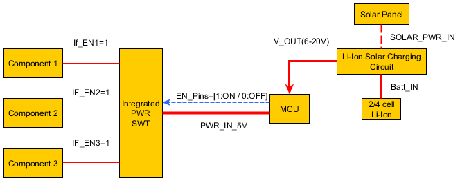
My aim is to regulate/control the power into each of the devices independently (i.e. Sensors and RF). These components share the same voltage line which is supplied through the MCU platform. I would like to integrate a power management module in between the device and the components in order to independently switch on/off components using a software defined trigger (e.g. digital input). Please consider looking over the diagram to get a better understanding of what I'm trying to do.

Could such system be implemented? If so, what would be the required parts that I need to get for:

- Integrated PWR Switch

- Li-Ion Solar Charging Circuit

However, if my design is incorrect, could someone please suggest an alternative? Thank you so much for helping out.

Kind regards,

  • Hi Amro,

    I cannot comment on the Li-Ion Solar Charging Circuit, but I can help you with the Integrated PWR Switch block.

    If you are trying to fan out and regulate a 5V power rail to different modules then this seems like a perfect application for our load switches!  I have put together a diagram showing how you might be able to accomplish this.

    Using the GPIO outputs from the microcontroller, the load switches can be turned ON or OFF which will allow the 5V power to pass through to the different components.  If you would like a recommendation on which load switches to use, you can provide the current consumption for each of the three components and I will get back to you with some recommendations.  A good load switch to start with would be the TPS22965.

    We also have dual channel and quad channel load switches which may be able to reduce your solution size and the total number of components.  For dual channel devices, you can take a look at the TPS22966 and TPS22968.  These devices incorporate two switches in one package and have two separate GPIO enable pins to pass through power.

    The TPS22994 is our quad channel device which has four switches integrated into it.  Rather than using GPIO controlled enable pins, this device uses I2C to turn ON/OFF each of the integrated power switches.

    Please let me know if you have any further questions.

    Thanks,

    Alek Kaknevicius

  • Hi Alek. Thank you so much for your detailed solution. It is exactly how I envisaged it.  I believe a switch capable of supplying 2~3 A will be sufficient at this stage. I will probably need individual switches at this stage, and eventually migrate to a dual/quad channel ICs. Would you be able to recommend a single channel IC at this point? 

  • Hi Amro,

    I would be happy to provide you with some recommendations.

    If you are looking for a basic load switch which can pass through 2-3A at 5V, then I would recommend the TPS22964C.  This is a small, WCSP device with only an input pin, output pin, enable pin, and ground pin.  Because the resistance of the part when turned on is low (13mΩ at 5V), the voltage drop across the device should be minimal even at higher currents.  The controlled slew rate will help in minimizing any inrush current generated by a high load capacitance and the quick output discharge feature (QOD) will pull the output low when the device is turned off.

    If you are looking for a few more features, then we have the TPS22954 which is available in a plastic package.  This device has a CT pin which allows you to adjust the rise time of the output and also features a power good pin which will send out a signal when the voltage on the output has reached 90% of its final value.

    Please let me know if either of these load switches would work or if you have any questions about any of the features.

    Thanks,

    Alek Kaknevicius

  • Alek, thank you so much for your assistance. I'm leaning towards the first option, but it doesn't hurt to get the second option as well.