Hello,
I am trying to do a step down buck converter that connects a battery pack to a output charge. My battery works from 60 V to 40V as it goes discharging, and I need to get 24V in the output charge, the maximum current is 12A and the working frequency is 100kHz.
When using the lm5117 IC, I only get in the output charge something like 3.5 V instead of the 24V expected.
I changed the working frequency to 20kHz and the charge too, with different values. I start with 100R then 20 R, 8R and 2R and the output had little variation. I change the inductor value between 240uF and 20uF and still get the same 3.5V in the output.
I added resistors to the mosfet (IRF451) gates of 4R.
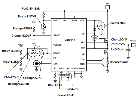
The values were calculated using WEBENCH and the LM5117 Quick Start Calculator given by TI and are described in the figure below. Almost all the components were bought regarding the Bill of Materials generate by the software. The ones that weren´t are Mosfet 451, inductor and Css. The schematic were import to Altium and the board was made from the beginning.
The components that aren´t illustrated on the picture are Cin=10uF, Cinx=100nF and Cout=300uF.
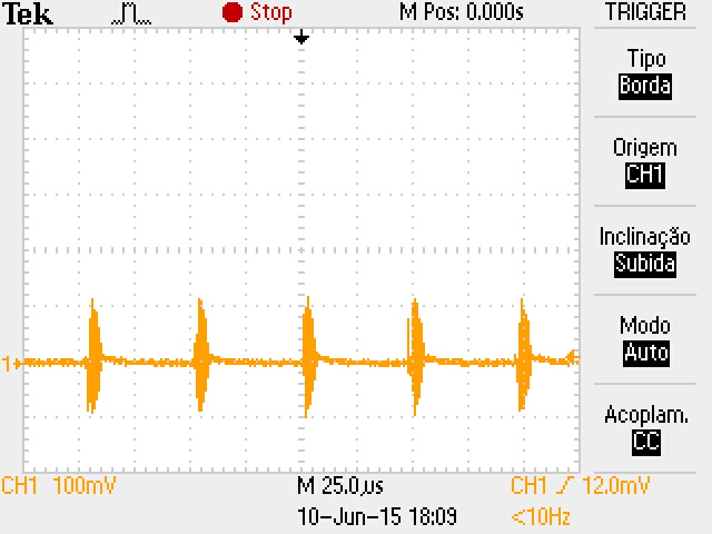
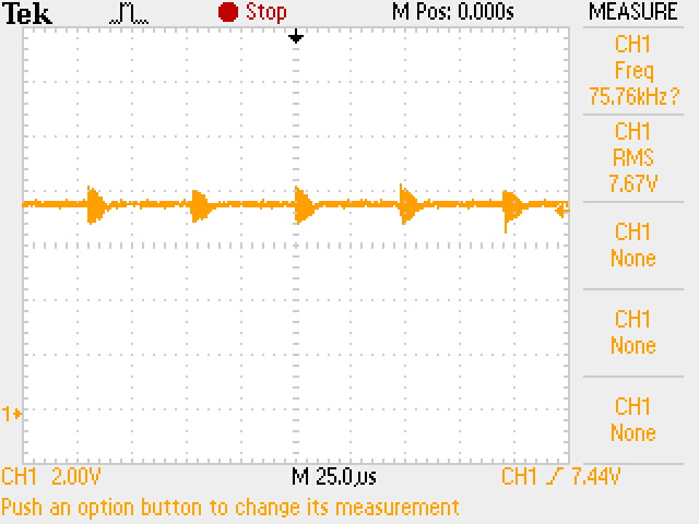
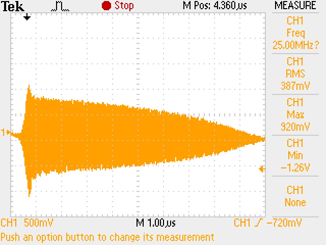
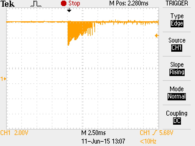
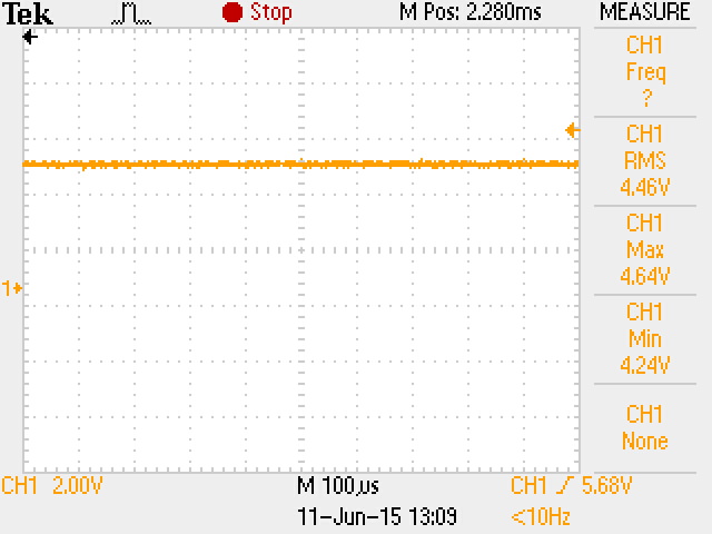
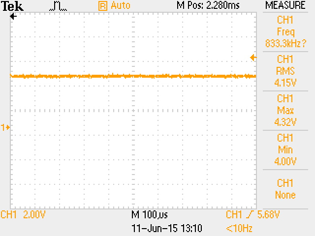
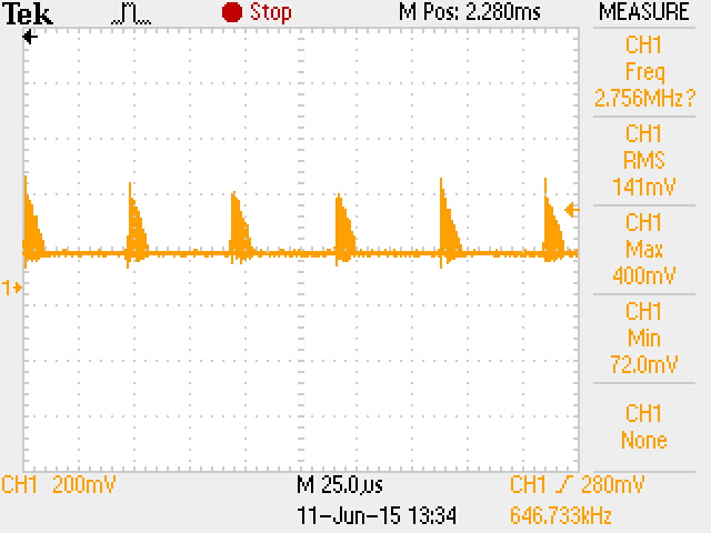
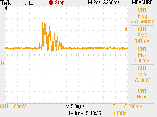
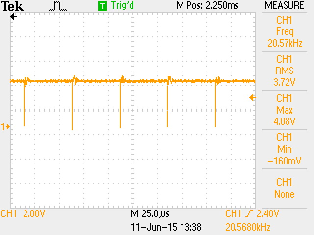
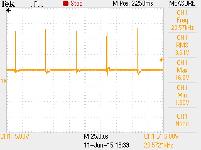
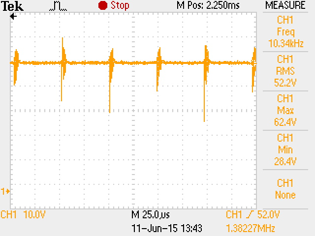
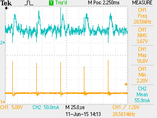
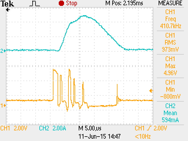
In the last picture I show the gate and Vds of the high mosfet, I think that Vg is correct but the mosfet isn´t polarized. Can you help me finding a solution?
Best regards,
João