This thread has been locked.

If you have a related question, please click the "Ask a related question" button in the top right corner. The newly created question will be automatically linked to this question.

LMR14206 hiccup at startup

Other Parts Discussed in Thread: LMR14206, LM2597

Hi,

I am using the LMR14206 for a 10-30Vin, 5V out followed by an LDO for 3V3 out.

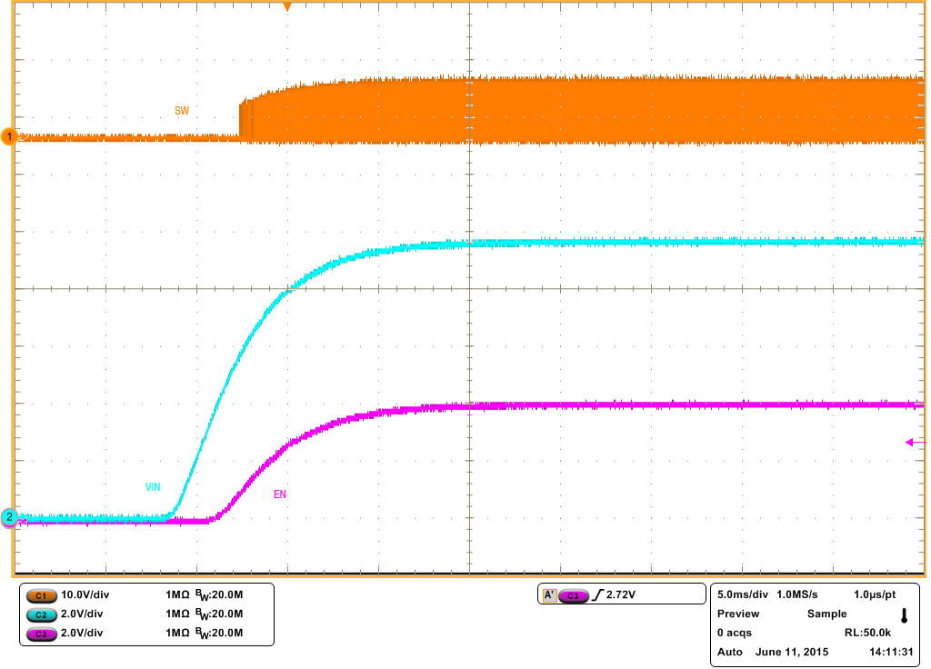
When the LMR14206 starts up with an input voltage lower or slightly above the programmed output voltage , the device starts working but exhibits a sort of hickup behavior.

When the input voltage is around 7.5V the device works correctly.

Is there no internal startup circuit that prevents the device from starting too early causing such behavior.

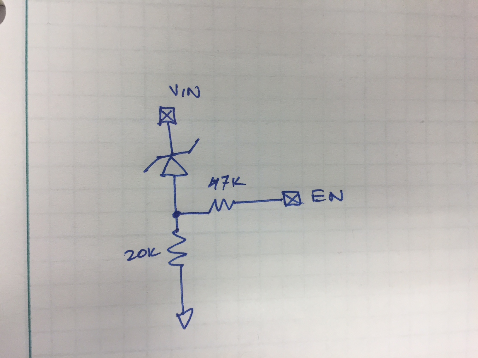
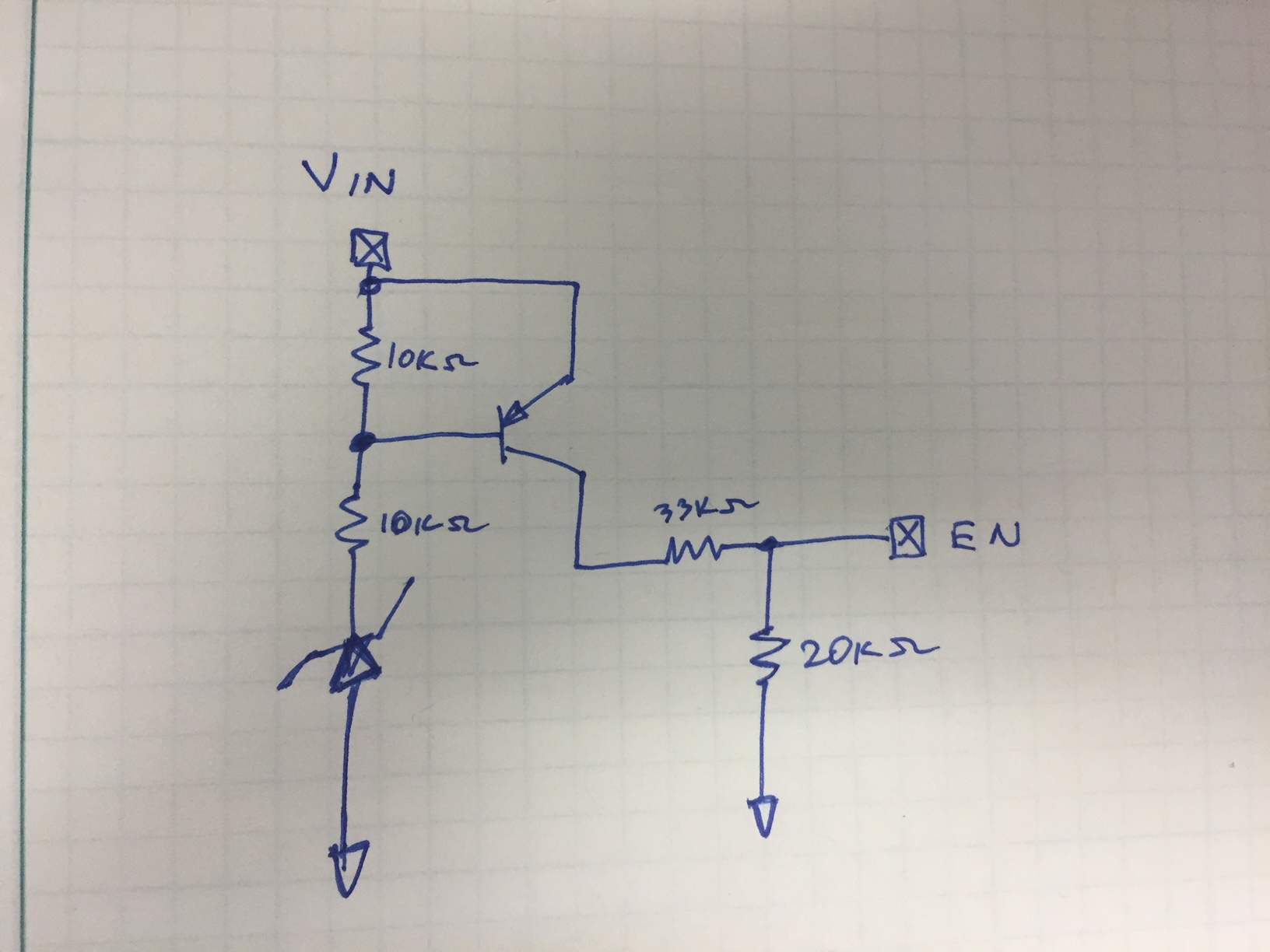
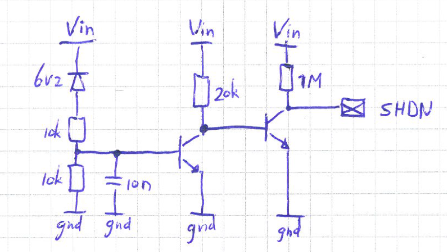
If this is normal behavior, do you have a recommendation for a circuit to make sure the device does not start up before Vin =>7.5V??

Below some pictures I took of the in/output voltages

  • Hello Jan,
    I think you forgot to put pictures. But unfortunately the part has an internal UVLO of 3.7V and this is fixed. I will ask around tos ee if there's a way to hack on an external UVLO. Adding an RC on the SHDN pin will give you an adjustable softstart but not UVLO.

    Regards,
    Akshay
  • Hi Jan, 

    The pictures did not get attached in your post for some reason. 

    Anyway, it looks like the LMR14206 has logic level enable pin and VIN UVLO at 3.7V typical. In your case, it is trying to start up as soon as Vin is around 3.7V (since EN is tied to VIN). At that point the regulator is probably trying its best running at maximum duty cycle. If the output is loaded, the current pulled from the input supply will be larger than expected, close to the load current. The "hiccuping" may be due to overcurrent on the input supply or due to the part running at max duty (although I don't think max duty should not really result in hiccup)...

    I found a couple of simple, external UVLO circuits in the LM2597 datasheet.  I briefly tried them in the lab today with the LMR device and they seemed to work.

    Here is the circuit from Fig 50 of the LM2597:

    Here is the startup waveform with that configuration. 

    Here is the circuit from fig 51 (but all ground referenced):

    And the startup waveform:

    The version with the BJT provides a better step in the EN signal. 

    Note that there is not much hysteresis with this circuit. I had 5V and 3.3V zeners in the lab stacked together in series. 

    I am sure there are other circuits out there that can also do this, may be more complex but with better precision and hysteresis. 

    Cheers, 

    Denislav

  • Hi Denislav,

    Turns out with above simpler UVLO circuits the device still switches on to early (resp at 4.7V and 5.0V for the circuit with transistor). So, we're now thinking of implementing attached circuit instead so that LMR device starts at 7.4V and is fully funcctional at 7.6V. Makes sense?

    Joost

  • Hi Joost,

    You should be able to adjust the voltage in the single transistor circuit by modifying the divider in the zener branch.

    Anyway, the circuit you posted should also work and may give you better accuracy. If you want, you can also add some hysteresis by feeding back some current from the output (/SHDN) signal. Here is an example:

    Cheers, 
    Denislav

  • HI Denislav, good suggestion on the hysteresis; now there's no more transitional area but rather fixed on/off points. Thanks, this works!