This thread has been locked.

If you have a related question, please click the "Ask a related question" button in the top right corner. The newly created question will be automatically linked to this question.

I want to design 20S Li-ion bicycle BMS

Other Parts Discussed in Thread: BQ76930

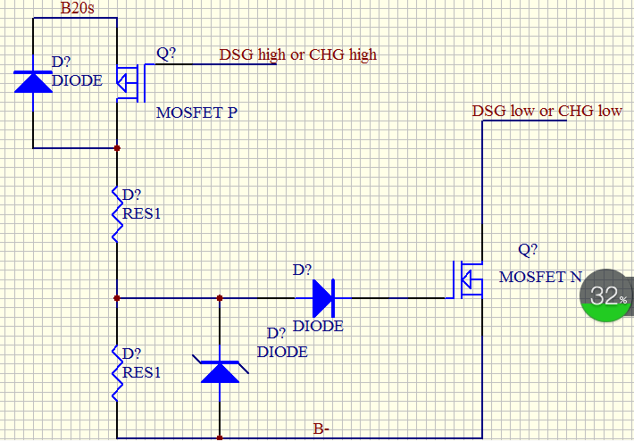
I want to design 20S  Li-ion bicycle BMS by two bq76930,How to connect the CHG and DSG pin by mosfet design?thanks!

  • You could level shift one set of FET drive signals such as the top part to the level of the bottom part, then combine with logic and send to FET drivers.  Or since the top part would do voltage and temperature monitoring only and those are typically slow, you could have your MCU watch the top part and turn off the FETs with it.  This would require that the software always run, if you choose this method be sure that it will meet your requirements.

  • like this?

  • That is the general idea but will need some refinement.  DSG and CHG are generated as positive voltages with respect to VSS, so you would want to compare the signals from the upper device to its VSS.  The connection shown for the P-ch would likely be on all the time.  DSG and CHG are also push-pull drivers so shorting the outputs with a FET is not recommended.  The desired function is to AND the top device "on" with the bottom device "on", then drive the FET gate high or low with that combined signal.  The CHG pull down is weak, be sure to consider that with your logic design.  For the driver REGSRC of the bottom might be a suitably reduced voltage from battery+, but remember that the gate voltage must be limited.  Be sure to watch the supply voltage range on the charge FET driver remembering that the gate voltage must be limited, the gate must go below VSS of the bottom IC (below battery-) to keep the FET off and that the signals will pull up to PACK+ when the discharge is off.   If you chose a high side switch the logic is the same but the FET drive will be different.

    Note that the internal load detect mechanism of the AFE will not be available when using external logic and drivers, the MCU will need to detect a load after fault through some comparator state or voltage measurement.

    With a different device and using separate charge and discharge paths an approach tested was described in http://www.ti.com/lit/pdf/slua637 but keep in mind that that device had a floating charge FET driver.