This thread has been locked.

If you have a related question, please click the "Ask a related question" button in the top right corner. The newly created question will be automatically linked to this question.

BQ24650 Charge Status Outputs

Other Parts Discussed in Thread: BQ24650

Hello Forum ,

I'm having a strange issue when charging a battery using the BQ24650 Evaluation board.

When I connect the charger to a power supply and a battery, both stat LEDS are turn on. But the Buck converter steps down the voltage to the MPPT voltage previously programmed and the battery is being charged.  So I'm waiting only to have the Charge Stat LED brighten (Set to low by the IC) but I have the two STATS brighten together (Indicating a charging and full charge state, both stats set to low by the IC). 

Do you have a comment on what is happening with the circuit? I cannot find a fault state regarding the two Stat pins to be Low. 

Thanks for your help

  • Hi Alb,

    I suspect a IC damage if both STAT1 and STAT2 pins are going low. Do you have the STATx pins connected to anything (like to GPIO pins of a MCU?)? If you exceeded the voltage on the STATx pins, or if you have the STATx pins connected to a MCU that can't tolerate anything higher than 3.3V, it's possible to see both LEDs lit during normal operation. What happens when you remove the battery (but input adapter is still present) during a charge cycle? Do the LEDs turn off?
  • Hello Again Smritri,

    The Stat pins where connected only to the LED's with a 10k ohm resistor as the EVM.

    The IC might be damaged and I could have made the mesuraments that you state but before testing the IC caught a little fire near the SRN and SRP pins as above:

    PCB soldered :

    PCB in CAD:

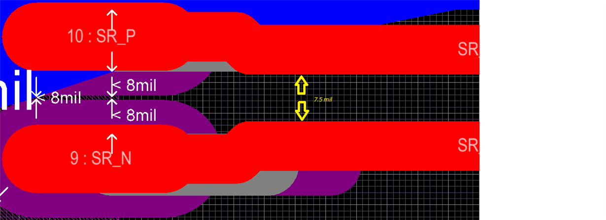
    Detail of SRN and SRP pins:

    Distance beetween pads of the IC = 8.858mil ( 0.225 mm)

    Distance between SRN & SRP tracks = 7.5mil ( 0.191 mm)

    Maybe was because it was hand soldered?

    Maybe the clearance is too low? What would you think was the problem?

    Another board caught fire. And the most affected part were on the pins 13 to 16. As you can see above 

    PCB soldered :

    PCB in CAD:

    Burned pin in schematic :

    In the case of this board damaged board, it worked at the beginning but when it failed,  the Charge LED stat blink at approx 1 Hz.

    I dont really have a clue why did this happen. 

    Please let me know your comments. Always a pleasure Smritri. 

    My best regards 

  • My guess is that there was a solder short somewhere (maybe between PH and the termal pad under the IC?). You need high current for a damage like that, and the SRN/SRP are not high current paths.
  • Yes you are probably right.

    For the SRN SRP pins maybe short circuit was mistakenly connected.

    Thanks Smritri ! The soldering will be more carefull.

    Any chance on reviewing the last Gerber that I send you? I you could please take a quick look it would be great.

    Regards