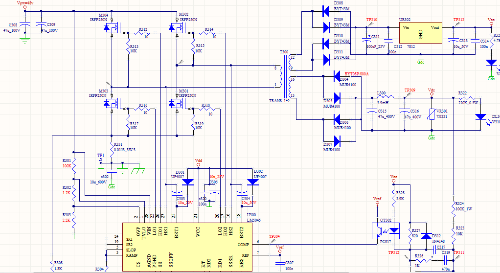
I designed an inverter application with LM5045 in full bridge topology and run it at frequency of 200kHz.
Here is a capture which red signal indicates on primary side transformer voltage.
But unfortunately I can't analyse in each part of this diagram which component is activated?
Are the pulses with nearly 500nsec width normal or unusual? Are they made because of body diode in MOSFET switches?
Does any body have a practical experimental figure of transformer voltage which helps me to compare with my figure?
how can I find out from this figure that the designed circuit is working correct or not?
Thanks in advance