This thread has been locked.

If you have a related question, please click the "Ask a related question" button in the top right corner. The newly created question will be automatically linked to this question.

Boost-mode, Isolated DC-DC confusion!! (UCC28600)

Other Parts Discussed in Thread: UCC28600

Hello,

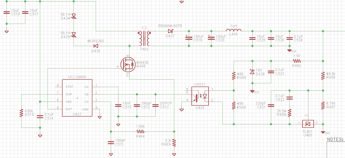
I am using the UCC28600 for a power supply with the following specs: 15-11VDC IN, Isolated 24VDC OUT @ 250mA. Please see the attachment below for a reference. The only changes I have made from the schematic is to short D434. The only reason I am using the UCC28600 in this application is because I am using it for the AC/DC converter on the same product and am trying to save $$ by not having to buy another controller.

The problem I am having is that I cannot get the circuit to operate in boost mode; my output is always ~2V less than my input. Even with no load attached, it uses alot of current, trying to hit 24V on the output but it just can't. When my input voltage exceeds 24V, the output stays at 24V, right on the dot. 

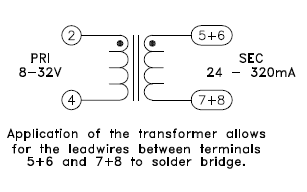
I feel there is some fundamental flaw with my circuit that does not allow it to run in boost-mode. Almost every buck-boost isolated flyback circuit I see uses a split transformer, unlike mine. However, I did find one circuit that uses a standard transformer, only adding to the confusion. Can anybody help me out? If I need to provide more information just let me know. 

  • Daniel,
    The transformer T402 is not wired up correctly. The secondary winding has the dot side connected to diode D437. This should be connected to the negative side of C519.
    If you attach your transformer data sheet, I can double check this but you need to mark up the schematic with the pin outs for the transformer

    john Griffin
  • I'm sorry, but I don't believe I wired it improperly. Take a look at the snippet I took from the transformer's datasheet. It shows the dots in the same orientation as I have it on my schematic/layout. Correct me if I'm wrong. (I also attached an image of my layout)

  • Well, it looks like you were right. Can't believe I've spent over 2 weeks trying to figure out what was wrong with the two power supplies I built using the UCC28600. Thanks for your help.
  • Daniel,
    I cant tell for sure but it looks like pin 4 of the transformer is connected to the drain of the MOSFET. If so, this would be incorrect. The easiest fix is to connect the secondary diode (D437) to pins 7,8 and connect pins 5,6 to output ground. Make sure first that secondary ground trace is completely disconnected from 7,8.

    I don't know what kind of transformer this is but make sure that it is suitable for the application.
    Use the calculator tool for the UCC28600 if you need help specifying this part.

    John