This thread has been locked.

If you have a related question, please click the "Ask a related question" button in the top right corner. The newly created question will be automatically linked to this question.

BQ24210: does not charge faster than ~90mA with 6 Voc solar panel

Other Parts Discussed in Thread: BQ24210

Hi


I am using the Demo Board BQ24210EVM together with a LiPo battery and a solar cell with 6 V open cirquit. The parameters are: Iset = 500 mA (default on the DevBoard), self-enabled (PG connected to EN), VDPM pin floating as suggested in the datasheet on page 20. I tried the TS pin at 30% of VTSB according to page 19 and the Limited Power Charge Mode with TS tied to VTSB. I even tried two units to make sure my unit is not broken.

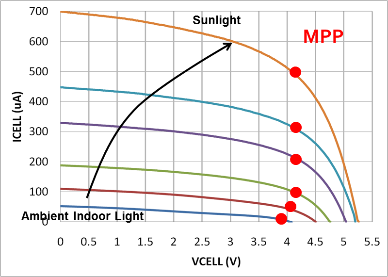
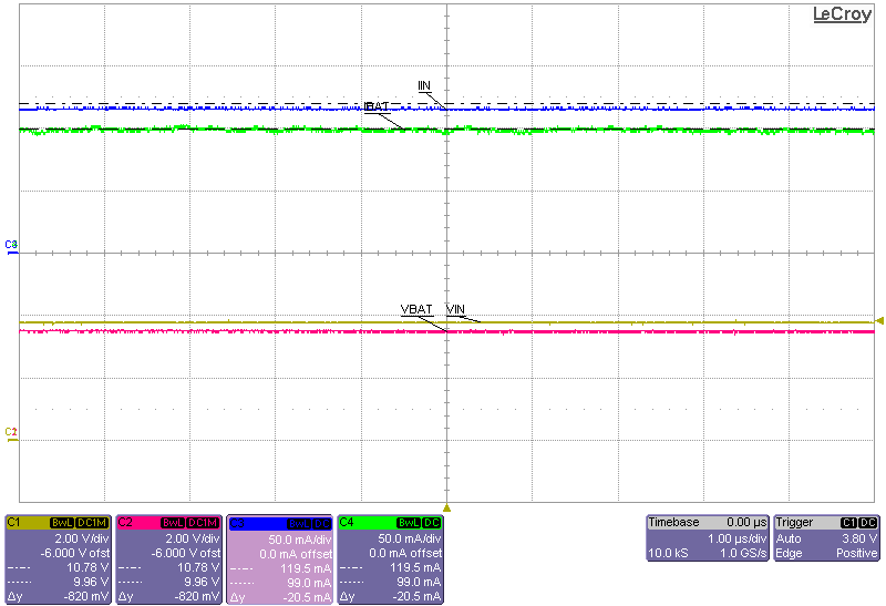
My problem: If I put the solar cell in sunlight anywhere between 40k and 90k lux, it always charges with roughly 90 mA. Even if I connect a second solar panel in parallel, there's not more. The battery voltage is 3.84V while charging, so it shouldn't be precharging or reach the end-of-charge voltage. Could the device be overheating and thus reducing the current? Or any other ideas what I'm doing wrong?

Thanks for your consideration!

--Sandro

  • Update: still not working.

    Meanwhile, I tried different resistors for Iset. With 7k9, it charged with up to 55 mA as it should. But with 490r (for 800 mA), it again got stuck at 88 mA -.-

  • Hi Sandro,

    I am having similar difficulties. I do not have the demo board, I have had to "breadboard" a sample device...

    I have a similar solar panel (~6V open-circuit, hand sized), and a 1100mAH LI-Ion battery. Using the BQ24210 datasheet, I have set the following parameters:
    * Iset - I need approx 300mA charge rate, Rset (Iset) value is 1k2 to GND -> 329mA
    * /EN -> connect to /PG so device only operates when solar power is available.
    * VTSB: my battery has a NTC resistor, approx 6.85kohm @ 45C, so RT1=30k ohm (3X10k). NB the datasheet is a bit obscure wrt these calcs; refer Fig 11, and "Electrical Characteristics (continued)" : "BATTERY-PACK NTC MONITOR". I have deduced that:
    VTSB - 2.2V
    V60C - 0.264V (12% of VTSB)
    V45C - 0.409V (18.6% of VTSB, mentioned as 0.186 in 9.2.2 Typical Application)
    V10C - 1.012V (46%)
    V0C - 1.254V (57%)
    * VDPM: using a current sink, I have characterised my solar panel as having a MPPT (max power point) voltage of ~4.6V (and 170-200mA available in full sun!) So, by 8.3.1 in the datasheet, I calculate Rvpdm = 7.3kohm. I used 3X 22k in parallel.

    My testing results:
    * with a bench supply, I have seen operation which appears to fit the design parameters above. I have also been "snookered"/fooled by some of the startup timers, etc! I can increase the voltage and current limit of the bench supply, and see that the device limits to approx 300mA, as required. In short, it all appeared to work.
    * But then I put a real panel in the sun, and at best I get 20-30mA charge - barely enough to cover my application's current use, so very little charge to the battery.

    I am left scratching my head, and wondering if the device is in a mode I am not understanding.

    Sorry, not an answer, perhaps even more questions...?

    thomasp
  • Hello Thomasp,

    Your first test result shows your circuit design is working. Your second test result shows your panel's current capability might not be high enough.

    First, the open circuit voltage and short circuit current of the panel varies with different light lux level. Thus the MPP voltage and current varies with lux level as well. What lux were you tested in? What is your panel's current capability at MPP? The charge current should be the VIN*IIN*efficiency / VOUT. Also, please make sure that your battery pack is not overheating by meausring the voltage on TS pin. Make sure it is within the operating window.

  • In my case, the solar panel is not the limiting factor: At 90k Lux, the charging current is ~90 mA, the battery voltage is still at the same 3.8 V, and the cell voltage is >5 V. So the BQ24210 obviously left battery tracking mode and switched to current limiting.

  • Hi Jing,

    thanks for your reply.

    > First, the open circuit voltage and short circuit current of the panel varies with different light lux level. Thus the MPP voltage and current

    > varies with lux level as well. What lux were you tested in? What is your panel's current capability at MPP? The charge current should be the

    > VIN*IIN*efficiency / VOUT. Also, please make sure that your battery pack is not overheating by meausring the voltage on TS pin. Make sure

    >  it is within the operating window.

    By using a variable current sink, I have established that the peak current of the panel is approx 160-180mA, with a MPP voltage of approx 4.6V. The panel is approx 6V open circuit.

    I cannot speak for the Lux under these conditions, except to say that I measured it at midday, under a cloudless  African sky (30 deg south), pointed directly to the sun.  I cannot imagine better conditions.

    WRT the battery pack temperature, my previous post details how I arranged this. Then, by measuring TS, I can see that the battery is in the 15-20C area. I "confirmed" this by handling it - cool to the touch. Given the low charge current, and that the application board was using most of the current to run, this is not surprising.

    > Your first test result shows your circuit design is working. Your second test result shows your panel's current capability might not be

    > high enough.

    I would not entirely agree. My understanding of the VDPM resistor, was that is basically set the MPP voltage. So, I expected operation thus:

    * assuming a flat (2-3V) or reasonably charged battery;

    * assuming solar panel voltage to be 6V, and in full sun view;

    * /PG connected to /EN

    * charger will draw current until panel voltage falls to MPP voltage, set by VDPM resistor (for my app. ideally 4.6V);

    * limited by the Iset resistor to a maximum charge current;

    * limited by/at temperature extremes;

    * limited until Vbatt = 4.2V, then in constant voltage mode, and panel current falls off;

    * finally terminated when Iterm current reached.

    I have verified that Iset works, by using a bench supply. I have verified that the voltage on TS is as expected. However, I have used 100R, 1500R, 7333R (3X 22K in parallel), and open circuit in the R_VDPM position, and there is no change to the MPP voltage - I tested this with a bench supply current limited to 100mA and 150mA.

    So, 2 questions:

    1) Am I doing the MPP voltage setting (R_VDPM) wrong?

    2) Am I using the correct part? Or am I misunderstanding the operation of this part?

    Thanks once again for your help,

    Thomas Page

  • For example, as indicated in the plot above, at VOC, the panel does not output any current. Depending on panel manufacture difference, typically, the panel outputs maximum power when VCELL is around 80% of VOC. As panel output current increase, the cell voltage decrease. When the panel reach its max current, the cell voltage drops close to 0V

    You mentioned "by using a variable current sink, I have established that the peak current of the panel is approx 160-180mA, with a MPP voltage of approx 4.6V". Do you mean that when the panel is outputing 160 mA, your measured panel voltage is 4.6V?

    The MPP threshold set by VDPM is used to preventing the input source collapsing by excessive load. You can test it by limiting the input current and then increasing the load current. To test you can set the input power supply to 5V and current limit to 100mA. Then connect a source meter to VBAT. Set the sourcemeter Vsrc to 4V and current to 100 mA or higher. Then measure the input voltage with a volt meter, it should drop to the VDPM setting. The reason you do not see in put voltage drop to MPP on the bench is because you are not pulling excessive load to cause the drop on VIN.

    Below is my test result with bq24210EVM and IXYS SLMD481H08L solar cell. VOC = 4.7 @ 30k LUX. I set VDPM  = 3.8V with 2K ohm resistor. VBAT is set to 3.5V. Charge current is able to reach 99mA.