This thread has been locked.

If you have a related question, please click the "Ask a related question" button in the top right corner. The newly created question will be automatically linked to this question.

TPS73533 Verification

Other Parts Discussed in Thread: TPS735

Hello all,

I'm using the TPS735 to convert the 5V input from a microUSB input to 3.3V. Could someone verify whether the topology of our circuit is correct?

For background: BP_VCC_5V is the 5V input from another booster pack. D1 and D2 are two Schottky diodes to supply the voltage of whichever is higher, the 5V from the USB or the 5V from the board.

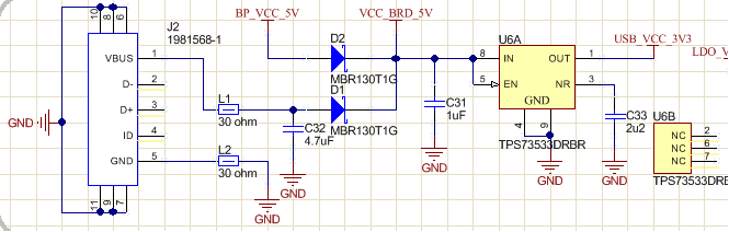
Also, a side question: I notice that there are two available packages for the TPS735: a DRB (8 pin one I'm using), and a DRV (6 pins). From the data sheet I can see the DRB has better thermal resistance. Is there any other differences about them that I should take into consideration?

Thanks,

John

  • HiThe appropriate apps engineer has been contacted. Thanks.
  • Your question will be moved to the appropriate forum and they can give you a more complete answer but generally speaking the thermal resistance is the only difference assuming space isn't a constraint. If you use the larger package it will run only slightly cooler and you could argue it might be a bit more reliable, this is a function of the load, board layout, and environment of your application. If you have the space, then I would suggest going with a bigger package. If not then it go with the smaller. The package thermal resistance is very close to each other.
  • Hi John,

    The above comments on the differences between the two packages are correct. Both packages will have the same performance for the electrical characteristic specs; however, if laid out properly, the DRB package will run slightly cooler. Multiple packages are commonly offered as a convenience to our customers; however, space and thermals are the key differences.

    As to your schematic:

    A capacitor on the NR pin should be limited to 0.01uF.

    A minimum of a 2.2uF capacitor is required on the output pin to assure stability.

    Very Respectfully,
    Ryan
  • Jennifer, fhoude, Ryan,

    Thank you all for helping confirm. Ryan I've made the suggested changes to the capacitors in the schematic.

    Best regards,
    John