This thread has been locked.

If you have a related question, please click the "Ask a related question" button in the top right corner. The newly created question will be automatically linked to this question.

[BQ24251] does not start to charge in the stand-alone mode.

Other Parts Discussed in Thread: BQ24251, BQ24251EVM-150

Hello~

I need your help for battery charger.

Below is my schematic of BQ24251 and is using the QFN package.

NTC is not using and rest of resistors are 20K & 20K such as bq24251EVM-150.

Test procedures are as below.

1. Insert the battery.

2. Connect the AC adapter.

3. BQ24251 does not start to charge the battery (As I understand, this is stand-alone mode.)

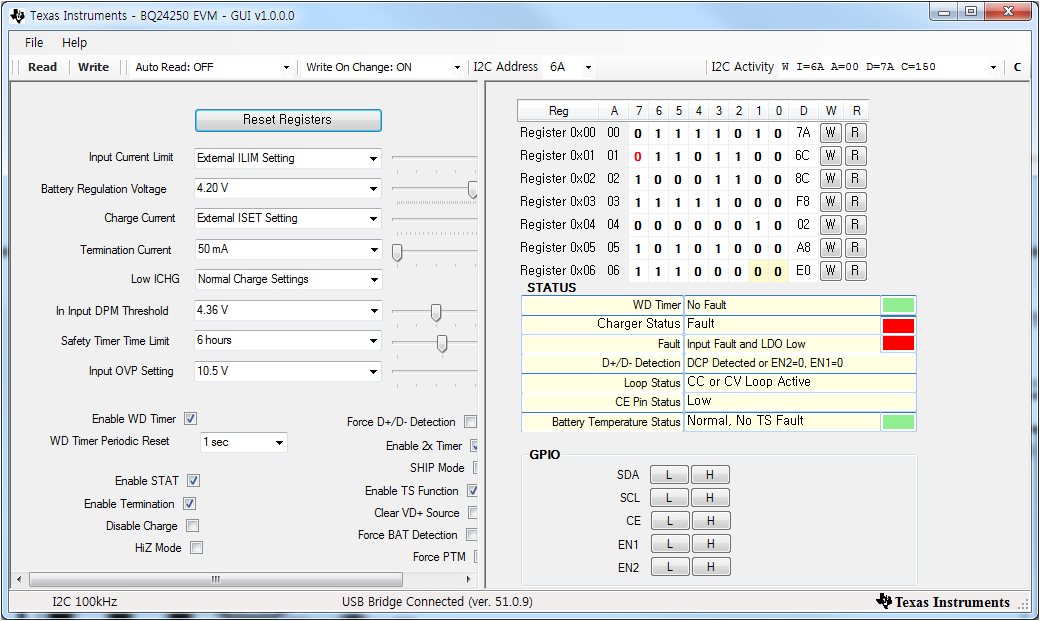
4. In the above condition, /CE input is "low", /PG output is also "low", and LDO pin has 4.9V output.  VIN = 5.2V, VSYS = 4.3V, but STAT pin is "high".

5. After system booting, processor send the I2C command. (As I understand, this is host mode.)

6. Reset and turn off the WD timer & TS function by I2C communication.

7. BQ24251 is starting to charge the battery, normally.

8. Removed the battery as well as AC adapter.

9. Insert the battery => System booting => Read the I2C register of BQ24251.

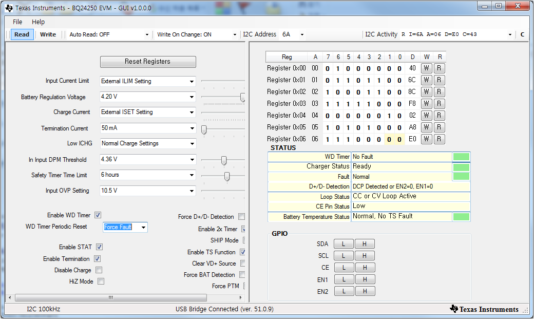
   - 00h --> 40h (0100 0000b) <== No fault & Ready & Normal
   - 01h --> ECh (1110 1100b) <== B7 value seems to be wrong.
   - 02h --> 8Ch (1000 1100b)
   - 03h --> F8h (1111 1000b)
   - 04h --> 02h (0000 0010b)
   - 05h --> A8h (1010 1000b)
   - 06h --> E0h (1110 0000b)

10. Insert the battery => System booting => Connect the AC adapter => Read the I2C register of BQ24251.

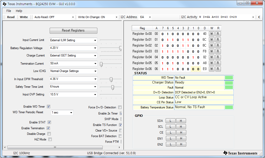
   - 00h --> 74h (0111 0100b) <== TS fault
   - 01h --> ECh (1110 1100b) <== B7 value seems to be wrong.
   - 02h --> 8Ch (1000 1100b)
   - 03h --> F8h (1111 1000b)
   - 04h --> 02h (0000 0010b)
   - 05h --> A9h (1010 1001b) <== TS temp > Thot
   - 06h --> E0h (1110 0000b)

11. Insert the battery => System booting => Disable the WD timer & TS function by I2C command => Connect the AC adapter => Read the I2C register of BQ24251.

   - 00h --> 10h (0001 0000b) <== WD disable & Charging & Normal
   - 01h --> ECh (1110 1100b) <== B7 value seems to be wrong.
   - 02h --> 8Fh (1000 1111b)
   - 03h --> F8h (1111 1000b)
   - 04h --> 02h (0000 0010b)
   - 05h --> A0h (1010 0000b) <== TS disable & Normal, No TS fault
   - 06h --> E0h (1110 0000b)

I cannot understand why this behavior is happened.

Would you please be able to think the expected cause?

Thanks... C.W. :)

  • Are you certain the /CE pin is low during standalone mode? If so, can you read the registers before you do any writing to the I2C registers? This includes sending the watchdog timer write. This will give me the status of the IC in standalone mode.
  • Hello, Jeff~

    As you can see the attached schematic, /CE pin has always 'low' with 47K pull-down resistor.

    Below is I2C register which was read by BQ24250EVM software.

    ==================================================

    Test procedure (1) is...

    1. Remove the all power sources.

    2. Insert the battery

    3. Connect the USB-TO-GPIO to BQ24251's I2C.

    4. Running the BQ24250EVM software.

    5. Read the I2C register. (Just click the "Read" button)

    6. Read result is as below.

    ==================================================

    Test procedure (2) is...

    1. Remove the all power sources.

    2. Insert the battery.

    3. Connect the USB-TO-GPIO to BQ24251's I2C.

    4. Running the BQ24250EVM software.

    5. Insert the AC adapter.

    6. Read the I2C register. (Just click the "Read" button)

    7. Read result is as below.

    ==================================================

    Test procedure (3) is...

    1. Remove the all power sources.

    2. Insert the battery.

    3. Connect the USB-TO-GPIO to BQ24251's I2C.

    4. Running the BQ24250EVM software.

    5. Insert the AC adapter.

    6. Remove the AC adapter.

    7. Read the I2C register. (Just click the "Read" button)

    8. Read result is as below.

    I hope that these test results are helpul to you to expect the cause.

    Thanks... C.W. :)

  • Please Change the WD Timer Periodic Reset drop down box to Force Fault then power cycle the IC and then click read all. This will give the status in standalone mode. In the screen captures above, the WD timer bit is being written so the IC in in HOST mode.
  • Hello Jeff.

    We were read the I2C register with reference to your advice.

    ==================================================

    <I2C read procedure -1->

    1. Remove the all power sources.

    2. Running the BQ24250EVM GUI.

    3. Insert the battery.

    4. Clcik the "Read" button in the GUI.

    5. Change the "WD Timer Periodic Reset" value to "Force Fault".

    6. Remove the battery

    7. Re-insert the battery.

    8. Clcik the "Read" button in the GUI.

    9. Read result is as below.

    ==================================================

    <I2C read procedure -2->

    1. Remove the all power sources.

    2. Running the BQ24250EVM GUI.

    3. Insert the battery.

    4. Clcik the "Read" button in the GUI.

    5. Change the "WD Timer Periodic Reset" value to "Force Fault".

    6. Remove the battery

    7. Insert the AC adapter.

    8. Re-insert the battery.

    9. Clcik the "Read" button in the GUI.

    10. Read result is as below.

    ==================================================

    <I2C read procedure -3->

    1. Remove the all power sources.

    2. Running the BQ24250EVM GUI.

    3. Insert the battery.

    4. Clcik the "Read" button in the GUI.

    5. Change the "WD Timer Periodic Reset" value to "Force Fault".

    6. Remove the battery

    7. Re-insert the battery.

    8. Insert the AC adapter.

    9. Clcik the "Read" button in the GUI.

    10. Read result is as below.

    ==================================================

    In addition to the above results, I've added several comment.

    When we only connected with battery, "Read" operation has no problem.

    In case of connecting the AC adapter and battery, or Connecting the AC adapter only, we always had problem to read the I2C register.

    For <I2C read procedure -2-> case, we have tried several times to get the results.

    For <I2C read procedure -3-> case, we also have tried several times.  But we just read the 0x00 & 0x01 addresses as a result.

    In the Host mode with "disable WD timer" & "disable TS function", we never met the problem for I2C communication.

    Thanks... C.W. :)

  • Hello~

    Do you have any comments or suggestions for our issue?
    If you need additional information to solve our problem, please let me know.

    Thanks... C.W. :)
  • Hello, Jeff~

    We are waiting for your comments or suggestions.
    To solve the problem, please let me know if you need additional information.

     Thanks... C.W. :)

  • In standalone mode, the input current limit is controlled by D+/D-. In addition, if the battery is a good battery (i.e. V(BAT)>~3.6V) and an SDP source has been identified by the D+/D- circuitry, then charging is disabled. Once you enter host mode, good battery/weak battery is no longer relevant and input current limit is controlled by the register. Since your charger works as soon as you go into host mode, that is the only thing that I can think of that would prevent charging. But, when you read the I2C registers from standalone mode (i.e. no watchdog bit writing but watchdog enabled), they show DCP as the D+/D- identified source. DCP ignores battery voltage so you should be charging. Oscilloscope plots showing V(IN), V(BAT), I(IN), I(BAT) just below and after you enter host mode might be helpful.
  • Hello, Jeff.

    We found root problem for our issue.

    We had soldering problem between NTC network and BQ24251 device.

    Now BQ24251 is working properly without TS fault on the Standalone mode.

    I'm sorry to bother you.

    Thanks... C.W. :)