This thread has been locked.

If you have a related question, please click the "Ask a related question" button in the top right corner. The newly created question will be automatically linked to this question.

confusion in UCC28711 datasheet & TI design documnet tidu412a

Other Parts Discussed in Thread: UCC28711

Hi,

the confusion is in Na/Ns (aux to secondary ratio).

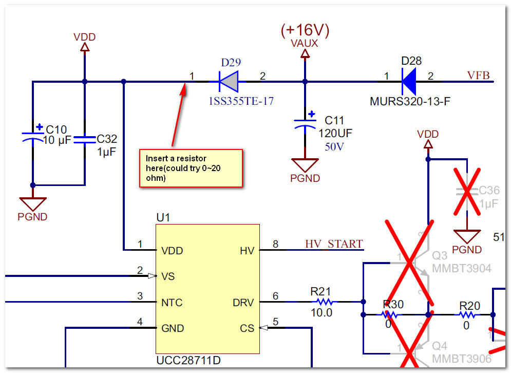
In tidu412a, while finding this ratio , voltage on auxiliary side is taken as 16V.

while in UCC28711 datasheet voltage for auxilliary winding taken as VDD(off) (8 V)minimum voltage for IC.

which one to be followed?

Please help.

Regards

Raja Saha

  • Hi Raja,

    I am moving this post to TI Power Management's "AC/DC and Isolated DC/DC" forum.  You will find support for the UCC28711 device there.


    Thank you,
    Brett

  • Hi Raja,
    I don't follow your question. Could you clarify it?

    Br
  • Dear Sir,

    I am using tidu412a design document from TI for my 137 watt SMPS.

    In this design, page no 19, equation 21 , to find a2 ( turn ratio of auxilliary to secondary) Vddmin is taken as 16V.

    wherehas in UCC28711 datasheet ( in page 20, equation 17 ) the same Nas is calculated by considerig VDDoff which is 8V.

    Then which things to be follwed to determine the turn ratio between aux and secondary.

    Hope it is clear now.

    Regards

    Raja Saha

  • Hi Raja,
    Yes, they are using different ways to decide the Ratio.
    If use the UCC28711 datasheet's method, that means the minimum VDD voltage could be almost 8V which is near to the VDDoff threshold if there is not much leakage energy.
    If use the Tidu412a's method, the minimum VDD voltage could be almost 16V which leaves enough margin.

    My suggestions are you could use a value little higher than 8V to decide the ratio. you may choose 10V or 12V to calculate.
    However you must measure the real VDD voltage at the full load and no load to make sure the VDD votlage always in the working range.


    Br
  • Yes sir, you are correct.

    To me , it was taken 16V ( which is also true in any other flyback design) as it will keep the controller in safe side to get turned off. But I have designed a flyback SMPS of 150 watt with following a design of tidu412a. My bias winding voltage is coming almost double ( 30V) to give me 110V secondary output.

    If you allow I can share the xmer design also.

    Please help.

    Regards

    Raja Saha

  • Some ways to decrease the voltage at full load.
    1. increase the resistor series with the aux diode.
    2. Decrease the ratio of AUX:SEC
    3. Decrease the leakage inductance.

    I don't know the resistor value, you may try method 1 and Method 2 First.
  • I have exactly the same thing as said in point 1.
    By doing this the output(secondary) voltage is increased, but still the aux voltage is coming near 30V.
    It seems to me that number of turns in aux is more than the required.
    Here only I am confused, that I have followed the same rule in the design document but still the number of turns are not as per the requirement.
    Please help.
    Regards
  • Hi Raja,

    Which resistor were you adjusting?

    On TIDU412A , there is no such resistor.

  • Sorry Sir,

    I understood it wrongly.

    I chnaged the value of R26 of (tidu412a)to get my desired output voltage.

    Regards

    Raja