Because of the Thanksgiving holiday in the U.S., TI E2E™ design support forum responses may be delayed from November 25 through December 2. Thank you for your patience.

This thread has been locked.

If you have a related question, please click the "Ask a related question" button in the top right corner. The newly created question will be automatically linked to this question.

LM3150 won't power up

Other Parts Discussed in Thread: LM3150, LM5116

Hello,

 I have design PSU 5V/5A with LM3150 with WEBENCH® Designer. When I apply power on input LM3150 won't power up. I check with oscilloscope HG, SW and LG and I don't have anything on this pins.

This is schematic: http://prntscr.com/7sh3qg On input is 24Vac, bridge rectifier, 5x 1200uF and 2x 100nF. This part is "shared" with 2nd rail 12V/10A with LM5116.


Any1 can help me to figure why this PSU won't power up?

Thanks and kind regards,

 Mladen

  • Hello Mladen,

    I will forward this to the apps engineers responsible for this IC.

    By the way, I could not get to the schematic files...would it be possible to upload the schematic and board layout here on the forum?

    Cheers,
    Denislav
  • If you don't feel comfortable sharing in the forum please send the schematic to SimpleSwitcherApps@ti.com

    Marc
  • Hello Denislav and Marc,

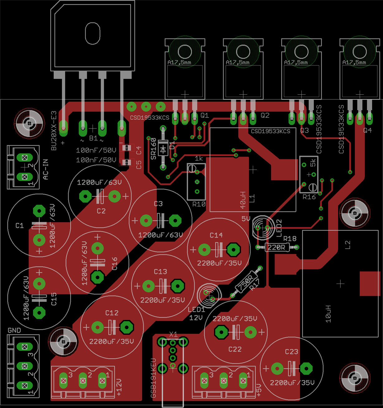
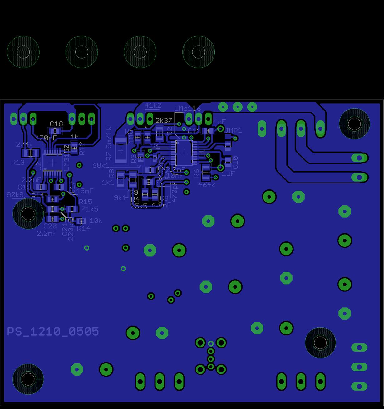
     I don't have problems with sharing design with forum, it's basically TI design :). Here are PCB layouts and schematic.

    Webench Design no. for LM3150 is 823311/59 LM3150MH/NOPB. I change MOSFET's, Cin and Cout. And I add one multi-turn trimmer for fine Vout adjustment. On schematic after bridge rectifier write +24V, actually input is 24Vac and after bridge is little less than 34Vdc. So in schematic +24V bus is actually +34V.

    Best regards,

     Mladen

  • Hello,
    Any news about my problem?

    Best regards,
    Mladen
  • I'm still looking through the layout but I saw two possibilities on the schematic.

    1)  First. Try Adjust the Soft Start Time.  With the 15nF capacitor, I am calculating 1.2ms startup. This is too fast for the amount of output capacitance you have. Try a 10 larger value.  It might be that the part is stuck under .6V reference and can't startup.

    2) What voltages are you seeing on other pins.?  Is the Vcc pin voltage around 5V?  If not is it Zero or some non-zerovalue.  If it is zero then maybe the part is not soldered correctly.

    3) En should work floating as you have in the schematic but perhaps there is some solder or flux on the pin.  Probe the pin and see if the part is being enabled.

    Marc

  • Hello,
    I put 100nF capacitor (this is closes to 150nF that I have atm). I was try with 120uF capacitor to check if it problem with amount of output capacitors. It did not work.

    I need 5 pcs of PSU. Only 1 of 5 was turn on and that was on where I did not solder 12V rail. It was working fine until I solder FETs for 12V rail, after that it's dead. I check voltages on pins, it's 0V or I get some times 0.6V on one or two PSU.

    I re-flow all PSU 2 times (some even 3 times). I will try one more time and will try with different FETs and then probe all pins and write results on paper.

    Mladen
  • Hello,

     I found "problem". If I apply 12Vdc on input ( I have 12Vdc power supply for testing) 5V rail works. If I apply 24Vac on input connector I hear something like spark and LM3150 die. Pin 1 (VCC) and 12 (BST) are shorted to GND pins ( they have1 ohms to GND pin).


    Is it possible that they are not wide voltage input range?

    Regards,

     Mladen

  • Based upon this failure,

    You need to add some ceramic Vin bypassing right next to pin2 to ground.  The pin is currently connected to a long trace Drain of the FET.  This is going to be noisy,  Try using a .47uF leaded ceramic. Also, this meand that you probably will want to add some ceramics from Vin to Ground across your High side and low side Fet to decrease the amount of noise in your layout.

    Regards,

    Marc

  • Hello,

     I have one more question about LM3150. I have 6pcs of LM3150 with Vcc pin shorted to SGND? I put 100nF for Css and 100nF from Vin to GND. Some of this 6pcs started for 1st time, some did not even start. The one that started 1st time, it was only time that they started. After disconnecting power, Vcc pin is shorted to GND.

    I assembly new PSU only 5V part. When I apply 12V dc, from PSU come high frequency noise for few sec, LED on output flash several times, and LM3150 die (Vcc pin is shorted to GND).