This thread has been locked.

If you have a related question, please click the "Ask a related question" button in the top right corner. The newly created question will be automatically linked to this question.

LM5069 Input surge clamping

Other Parts Discussed in Thread: LM5069, LM5069EVM-627, CSD19536KTT, TMP302, LM5066I

Hello,

I have a question regarding the input voltage clamping of the LM5069.

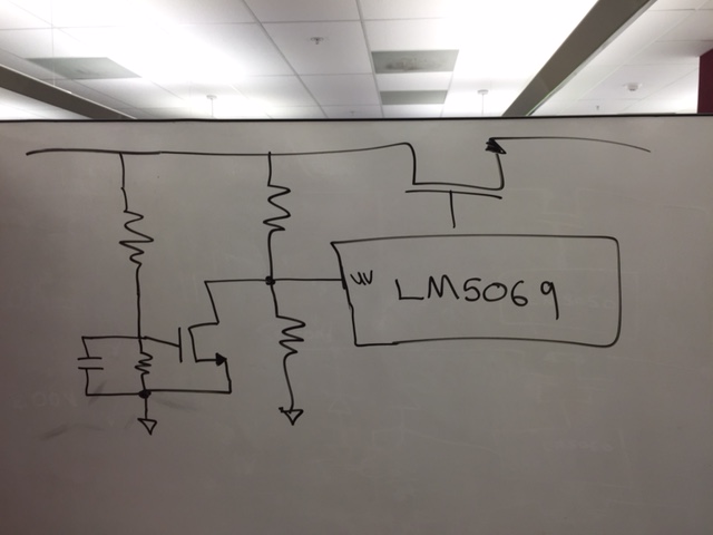
We have implemented a circuit similar the the EVM: LM5069EVM-627. Now i have a question regarding what happens when clamping a DC input voltage. 

The LM5069EVM-627 has the following specs:

  • Input voltage range: –40 V to +38 V
  • max – Output voltage clamped: +32 V
  • max – Current limit: 2.5 A
  • Q1 power limit: 30 W

When the EVM is powered with 36V, the mosfet will operate in linear mode and have a VDS voltage of 4V. When the output is loaded with for example 2A, there will be 8W of power dissipation in the mosfet. As far as i can read in the documentation of the datasheet, the power monitor is a fixed limit, which is configured to be 30W. Therefor the fault-timer will not trigger and the mosfet will burn after a certain time period, since it cannot handle this power continiously.

Am i misinterpreting the datasheet and will the mosfet be operated in SOA at all times and shutdown in this situation? If not what is possible to get a safeshutdown in this situation?

best regards,

Tom

  • Hi Tom,

    Your understanding is correct.


    Note that this LM5069EVM-627 was built based off previous testing of clamping, documented in more detail within this application note:

    (Can also be found at the LM5069 product folder: )


    Section 5, "Power Dissipation in Q1" discusses this topic which you brought up. Essentially if this is a case of concern for your application, then the design must consider the DC limit line of the MOSFET's SOA curve, and may need some additional heatsinking to help keep it operating within its SOA.

    - For reference, the CSD19536KTT is a TI NexFET with pretty strong SOA and low Rds-on. Note that even with 10V Vds, it can handle 30A of current DC (room temp, must be derated for extended temperatures):


    But to answer your question, if the circuit operates DC at a voltage close to the zener clamp and you wish for it to shut-off after a long period of time - then currently we do not have a tested solution.

    If you are willing to use the OVLO function for this then one option may be to set the OVLO to 32V but add a cap to form an RC filter delay.


    Or to keep OVLO function, a different method may be to add another resistor divider + NFET and tie it in to the UVLO using the same RC filter delay:


    Thanks,

    Alex


  • Thank you alex for your clear answer.

    I did some calculations on the suggestion of adding a delay in the overvoltage trip limit.

    However with all the tolerances of the capacitor, the OVLO threshold and the gate capping zener voltage, it was not possible to choose an RC delay that would not shut off in the surge condition during operation and turn off the mosfet in time when a DC overvoltage was applied from a cold start. (while not increasing the output capping voltage to have more margin).

    Therefor I decided to put in a temperature alert switch(TMP302D). The opendrain output interfaces to the UV pin like in your drawing. This prevents the mosfet getting too hot. I think this is the most robust solution, since the SOA protection of the LM5069 holds the mosfet safe in the short time (surges), while the temperature shutdown takes care of long time safety. (DC overvoltage)

    best regards,

    Tom

  • Hi Tom,

    I guess the corner case concern would be operating long time with a DC overvoltage (temp rise, but still below the TMP302 trip point), and then a surge of overcurrent which brings the MOSFET outside of its SOA.

    Also FYI for future reference, we have the LM5066I which is similar to the LM5069, but offers PMBus/I2C digital telemetry (current, voltage, power, energy reporting), a temp sensor to shut off from overtemp event (uses cheap external BJT to measure), and supports a 26mV current threshold instead of 55mV (so you can save on power loss).

    Thanks,
    Alex
  • Hi Alex,

    I checked that corner case by putting the tripping temperature as maximum ambient in the calculation sheet.
    It still has a derated SOA factor of 1.7, so that is more then OK.

    I did see that the TMP302 has very limited opendrain voltage so i cannot connect it directly to the UV pin.
    Also it might be a better idea to switch off the load, instead of disabling through the inrush circuit.

    The LM5066I has a nice feature set, but also alot more expensive and a bit overkill for our application.

    best regards,
    Tom
  • Sounds good Tom!

    Well then welcome to the E2E forums, I hope you have a good experience with the LM5069 and feel free to post a new thread if you have any additional questions.

    Thanks,
    Alex