This thread has been locked.

If you have a related question, please click the "Ask a related question" button in the top right corner. The newly created question will be automatically linked to this question.

TPS40210DGQR Not working Properly

Hi All:

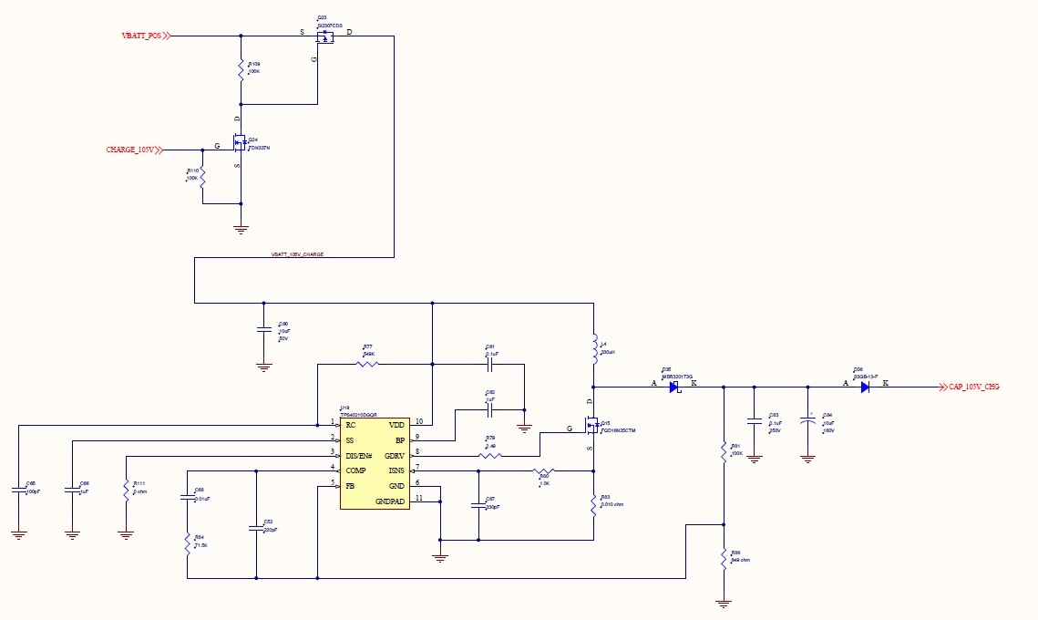
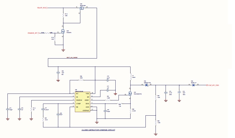
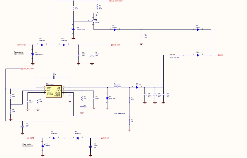
I'm using TPS40210DGQR to boost convert 12V battery voltage to 105V to charge a capcacitor which is used for opening a Solenoid.

The boost circuit is not operating properly and please look in to the attached circuit and let me know did I do anything wrong..

The problem the circuit does not charge the capacitor upto 105V only upto 35V it is able to boost and staying there..

Thanks 

  • Hi Yasin,

    The schematic connections look good. How were the values selected?

    It sounds like the part is hiccuping. You can confirm by checking the SS waveform and if it is you would see a sawtooth type waveform here.

    How large of a capacitor does it need to charge and is there anything else loading the output? The SS time may be too short requiring a large amount of current at start up to charge up the capacitor that then trips the current limit.

    This type of issue can also be layout related. I suggest comparing the layout to the EVM or datasheet to see if any improvements are needed.

    Best Regards,
    Anthony
  • Hi Anthony,

    Thanks for your reply. I using the output of this cap to charge two 470uF, 160V capacitors which is used to Open a solenoid. Also the same voltage is transistor zener regulated to 18V which is used to power my microcontroller as backup power source. Same like the above 105V boost circuit there is a 45V boost circuit which is used to charge a 2200uF capacitor which used for closing of a solenoid and this 45V is again buck regulated to 18V using a buck regulator and ORed using a diode with the above 18V. This 18V is used for generating power 3.3V and 5V . I have found route cause for the problem. In order to add more backup time I have added a additional capacitor (C90) in 18V Rail. When that capacitor is removed from circuit the entire circuit works fine.  Attached the 45V boost circuit and 18V buck circuit. Please let me know am I doing anything wrong.

    45V Boost Circuit

    18V Buck Circuit

    Thanks,

    Yasin