Hello,
I have used the LM5022 as the controller in a non-isloated, sepic power supply with the following specs: 10-15V IN, 12V out @ 5A max, 3A continuous. See the schematic below. The only permanent change I have made to this is so far is to add a resistor in between CS and the Source of the FET, I must have just missed that in my design.
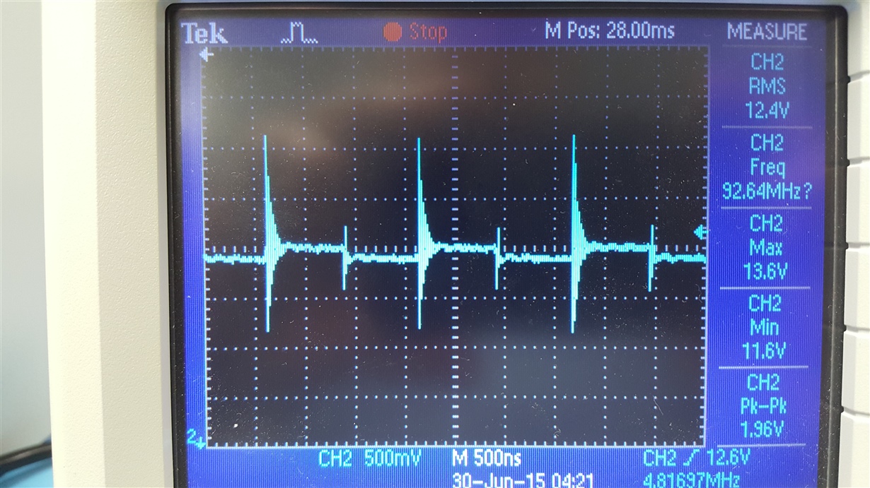
The supply works well, only ~100mV ripple, however I have this large ringing on the output. The noise is a very high frequency (>20MHz) and is in phase with the on/off periods of the switching FET. My scope probe has been modified to have a short reference lead, so I know that this ringing is real and not just due to my scope probe. Images from my oscilloscope are shown at the end of this post.
I have tried the following changes: changed the two parallel capacitors (C530/1) to higher values, changed the two inductors to higher values, altered the switching frequency by changing R495, and although some combinations did have an effect, none of them could eliminate the ringing. The only thing that could eliminate the ringing was to add an LC filter; this caused issues with switching between low/high loads, so I decided not to pursue that for my next revision.
Does anybody have any suggestions? I have a feeling it comes down to inductor selection/placement. I have seen conflicting theories about this. Some say the leakage inductance between the two should be minimized, and would recommend I use coupled inductors. Some say the opposite, that a high leakage inductance can be beneficial in this situation. I'm hoping someone here can help me figure this out so I can get this thing into production! All relevant images are below.
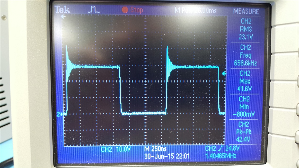
All of the images below are with Vin= 15V, Iout= 2A. The two inductors have been replaced with 10uH inductors...
2V pk/pk ringing on output:
Vds of the switching FET:


