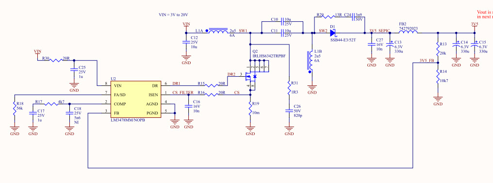
I use the LM3478MM/NOPB in a SEPIC converter. Vin=3V to 20V; Vout=3.6V; Iout 1.5A; fsw=300kHz. Please refer to the schematic and screenshot (The current (2A/div) is at the input of the board and the PWM is the gate of the Mosfet with a really bad GND connection... but the duty cycle is the main concern).
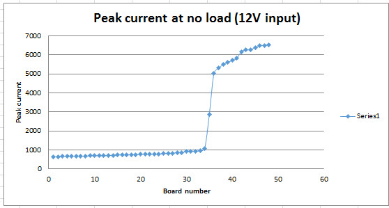
The controller tolerance seems to change the behavior at no load because the input current change from a board to another. The error amplifier have a tolerance of 4x between min and max values, and I think that might be the problem source. At each second, once the output voltage reach the min voltage, the controller restart (sort of burst mode) until the Over voltage is active.
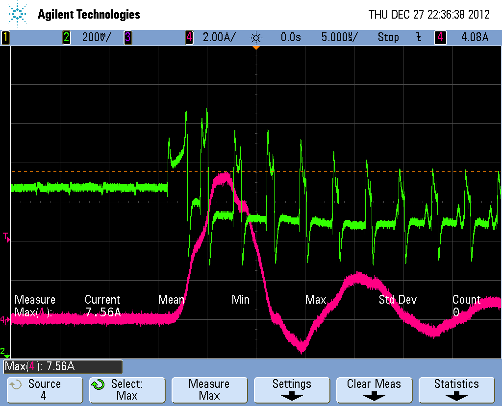
A "good" controller behavior at no load (12V input): At each second, the controller will pulse 70 pulses (approx) with a peak current of 500mA (input current)
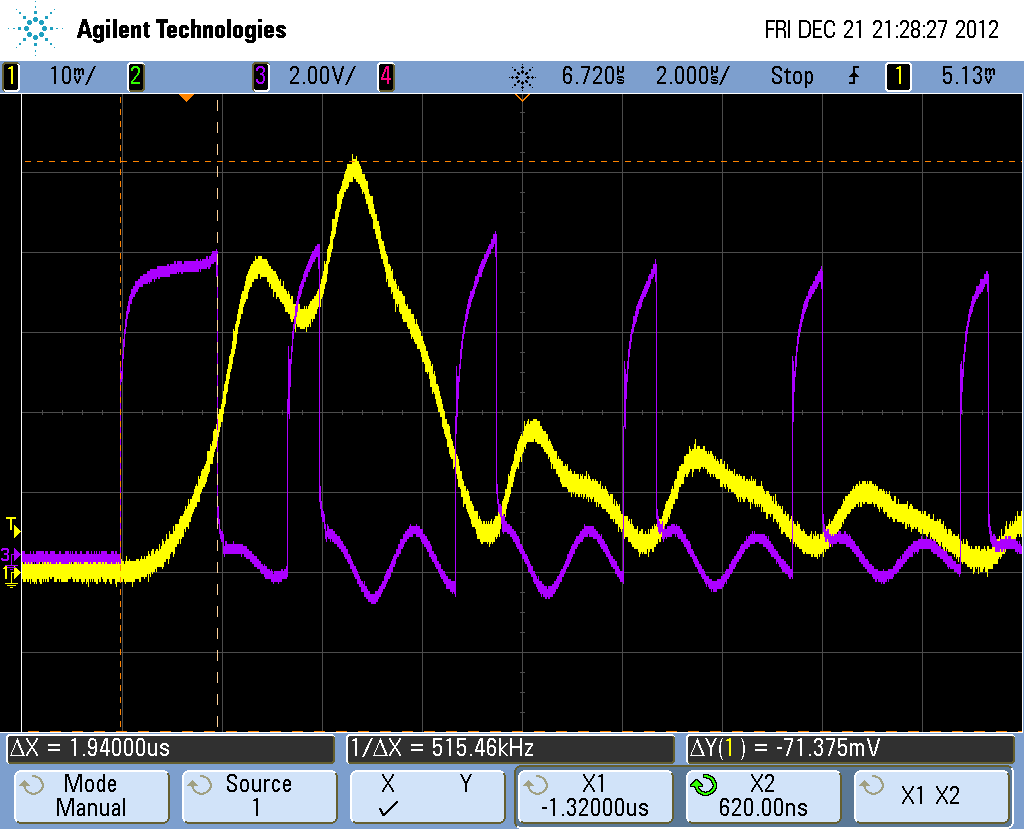
A "bad" controller behavior at no load (12V input): At each second, the controller will pulse 12 pulses (approx) with a peak current of 8A (input current).
I did try to change the Cc=100nF Rc=1k, that slightly reduce the peak current to 6A. The first pulse is quite long making the current to be high and the input inductor to saturate. The second to the last pulses seems to be controlled by the current mode.
By removing 2/3 of the output capacitor, the current is proportionally reduced.
The higher the input voltage is, the higher the peak current is.
Does the softstart should work during this pulse skipping mode ?
How the circuit can be improve the get 500mA for all controllers at no load ?
There are some space limitation on the PCB, to add minimum load to the circuit will be my last option if necessary.