This thread has been locked.

If you have a related question, please click the "Ask a related question" button in the top right corner. The newly created question will be automatically linked to this question.

lm25066 current limit

Other Parts Discussed in Thread: LM25066, TPS24770

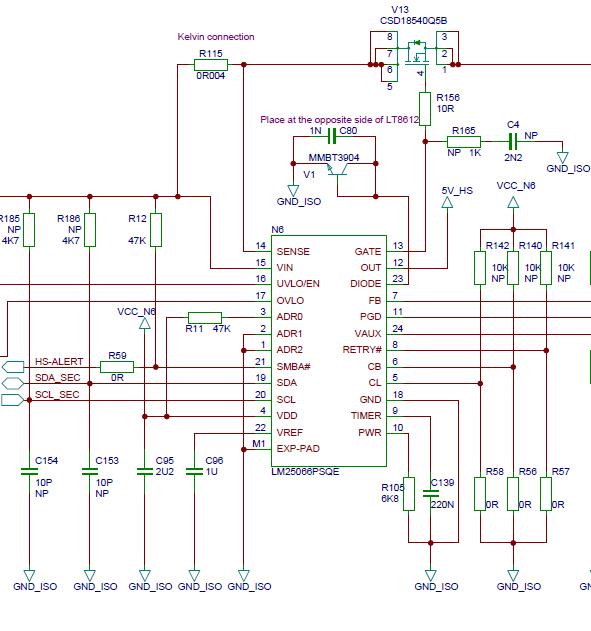
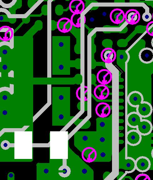
I have a LM25066 on the board, using a 4mOhm shunt for current limiting (typ. 6,25A). What I measure, is a much lower current 5,4A. In the figure below, you can see the layout. The “white” part is the shunt connected over the gray lines (inner layer) to the LM25066. We use a 1% shunt. Do you have an explanation for the mush lower current limit? Thank you for your answer in advance.

  • Hi Kamal,

    The best way to test if this is an IC issue or a layout/resistor issue is to measure the voltage directly at the pins of the LM25066 IC (can solder on two small, short length wires to the pins and measure with a multimeter, gradually raise the current, and see the point where it trips).


    Also note, 6.25A is typ, but min would be 5.8A to be within the EC table spec. Then another minor caveat is that the device will start charging the timer a tiny bit before the current limit begins regulating. This is done intentionally to ensure that the timer is always running whenever the controller is in regulation. This is explained a bit in the TPS24770 datasheet, page 13, section 9.2.6. So if you are testing by very gradually increasing the load current, then the device may trip slightly below the current limit regulation point. If instead you did a sharper increase in current, you would see the controller regulate the current at 25mV (typ).


    However, we would still not expect you to see 5.4A as the trip point. What size resistor is it? We have seen cases where resistors purchased as "1%" were not indeed 1%. Our experience has been that smaller resistors have tended to be less accurate (although all rated as "1%"). We tend to use 2010 or larger on all our EVMs. Sometimes manufacturers spec the accuracy at a given point on the resistor (such as the center of each terminal), so we would recommend checking its datasheet in case the manufacturer has guidance on where to connect for sensing.


    For best accuracy, I wrote this blog describing different layout techniques:

    There are many things that can go wrong when designing with a hot swap controller. For example, the hot swap can trip at an unexpected current value or a current monitor may report inaccurate measurements…
    By in Technical articles > Power management


    Since this application is low current (<10A) I would expect Figure 1) layout from the blog to be fine. However, this is close to what they are sensing (though not entirely the same), so I suspect it may be resistor or layout related.


    Again, the best way to check would be to use a multimeter and measure directly at the LM25066 IC. If you see the measurement there looks good for the trip point (around 25mV), then begin to measure elsewhere on the path (such as the vias, or at the sense resistor itself) to see where the IR drops are along the path.


    Thanks,

    Alex