This thread has been locked.

If you have a related question, please click the "Ask a related question" button in the top right corner. The newly created question will be automatically linked to this question.

BQ24610 capacitors

Other Parts Discussed in Thread: BQ24610

Hi Everybody.


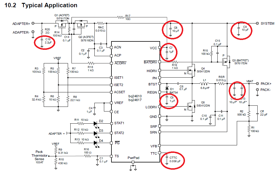
In BQ24610 datasheet's  Figure 19.System Schematic  capacitors  C16,C5,C8,C9,C12,C13 are polarized.

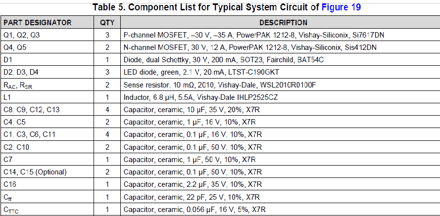
But in Table 5. Component list for typical system circuit of figure 19. all capacitors are listed as ceramic, which, as I know, are not polarized.

Pictures of typical application and list of components below.

So should I use polarized capacitors or not?

Thanks in advance.

  • Karlis,

    For TTC, REGN, and VCC, I recommend using ceramic capacitors. For the other caps that you have circled, it's up to you if you want to use ceramic or polarized caps. You decision will be based on the voltage, space constraints of your application (x, y, and z dimensions), and the amount of capacitance you need. Polarized caps like electrolytic or tantalum capacitors have a much higher capacitance density for a given voltage rating when compared to ceramic capacitors.

  • Thanks for the great answer!

    I have one last question about BQ24610 capacitors (i didn't want to start a new topic).

    As I understand capacitors C12 and C13 right before Bat+ are output capacitors.

    Which capacitors are the input capacitors, whose values I am calculating from datasheet? Are C8 and C9 the input capacitors?

    I hope my questions aren't too stupid.

  • You are correct about C12 and C13. In Figure 19, C8 is the input capacitor, and C9 is the system "bulk" capacitance. Input capacitor here is the input to the buck converter, and it can be comprised of more than one capacitor (0.1uF, 1uF, and 10uF, for example). The smaller value input capacitors are used to decouple high frequency ripple/noise and should be placed as close as possible to the drain of the high-side FET.
  • I'm very grateful, thanks for answer!