This thread has been locked.

If you have a related question, please click the "Ask a related question" button in the top right corner. The newly created question will be automatically linked to this question.

TPS61070 fails with modest current draw

Other Parts Discussed in Thread: TPS61070

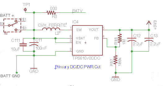
I'm using 2 x AA cells to power a small cct with two loads (processor and another chip) via the 61070, pretty much following the spec's reference cct/values. 

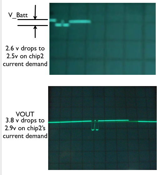
Using a 10uF tantalum input cap with a .1uF ceramic in parallel, a 4.7uH input inductor, and then for the output caps 2 x 4.7uF ceramic (0805).  The circuit is set up for 3.3V.  With just my processor loading it, it draws less than 10mA, and seems to manage 3.3V okay.  But I had to isolate the second chip to get to this point.  The second chip wants about 100mA to start then will settle to 30 or 40mA in a few seconds, but the 61070 doesn't seem to want to allow that.

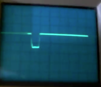
The output voltage drops to about 1.8V if I include the 2nd chip in the load.
The spec curves seem to suggest handling 150mA shouldn't be a problem, particularly with 3+ volts battery voltage available. Even when the 61070 gives up, the battery is still providing 2.9V, plenty I'd have thought.

My layout SEEMS to be following the guidelines. The output caps are about 2mm from VOUT pin. The resistor divider, perhaps 3.5mm from FB-pin.

Any suggestions what I can do to get a stable output at 3.3V to run my circuit?


Thx

Ross.

  • 1. please make sure the TPS61070 finish the startup before applying the load. This mean enable the load only when the output voltage of TPS61070 is ready. because the TPS61070 can't provide high load during its startup process.
    2. if the step 1 is not working. capture the waveform of VIN, VOUT, SW at the moment that the second chip is connected to the output of TPS61070. the waveform will help us to understand what happen
    3. please share the schematic and layout.
  • Thanks for the response, Jasper,

    1 - I've tried to only add the 2nd load after the 61070 is stable and happy. Upon adding it, the voltage drops, unable to handle the 50-150mA of extra current draw. I'm currently trying to start up the 2nd load in RESET mode, so it only pulls 35mA until it's released. Hopefully that'll be manageable. Will let you know.

    2. Will try to see the waveforms upon failure. I don't have a fancy enough scope to get the moment of failure but will see what I can get for before and after.

    3. Will try to share of the schematic/layout of that section. Hope those come thru.

  • Oops - in that schematic, the C12 and C13 values are actually both 4.7uF ceramic caps.
    C111 - is a 10uF tantalum, and C11 is 100nF ceramic.
  • 1. i think the oscilloscope should have the capture function to capture the rising or falling edge of the waveform. so you can capture the VOUT falling edge (3.3V -> 1.8V) and measure VIN and SW at the same time.
    2. what is the part number of inductor. i worry if the inductor is saturated.
    3. if you re-layout PCB next time, please place more vias beside the GND pin of the TPS61070 and output capacitor.
  • The inductor is a Bourns CVH252009-4R7M. It is a 4.7uH monolithic rated 1.1A and in a 1008 size.  Do you think more inductance there would be helpful? I'll explore that.


    Thanks for the guidance on the scope measurement, will see what I can do today, not sure I have the capability though.

    Good info regarding more vias - will keep that in mind if I have to re-spin the board.


    Ross.

  • 1. The inductor is good. it is not the reason of the failure.
    2. please try to increase the output capacitor.
  • More experimentation. I've tried increased output capacitor values, up to about 20uF. Hasn't seemed to help, and the 070 seems to get damaged often as capacitance gets higher level. So I'm going thru lots of parts at nearly $2 a piece these days. :(

    Trying another approach, I've used the voltage divider on FB-pin to raise the output voltage from 3.3V to 3.6V then using an LDO regulator to regulate back down to 3V for that second load. This almost works - the 61070 can hold the output voltage prob now, but as the 2nd chip (an RF device) tries to periodically use more current once per second, the current draw drops voltage by 1.5volts briefly, causing a reset of the 2nd chip. So still can't run it.

    The current without 2nd chip is only 17mA - with the second it's drawing 90mA, but needs another 150mA periodically for a few 100mSec.

    Q - do you have some guidance for maximum output capacitance, and maximum current the 61070 should be able to provide? The spec graphics seem to suggest 300mA should be do-able, at least for brief moments.

    -Ross.
  • actually i had try 300uF output capacitor before, and don't see damage in the EVM. and this device can output 300mA if the VIN is not too low.

    after you added LDO, had you capture the VIN and output voltage of TPS61070? i'm not understand your description clearly.

    Please try to increase the input capacitor, or change the input tantalum capacitor to ceramic capacitor. i guess maybe the problem is caused voltage unstable at VBAT pin because of the high ESR of tantalum capacitor.

    please place a 10uF ceramic capacitor closed to the VBAT pin (pin 6): one pin of the capacitor directly connect to PIN 6, the other pin to the GND plane

  • Thanks again for your replies, Jasper.

    Good to know that large output capacitor is not a problem for the chip. It must have been a coincidence that chips failed a couple of times when i was using higher caps.

    I tried your suggestions. I moved the input cap right up against the pin6. I tried it using only ceramic cap and not tantalum. I also tried much larger capacitance than I've tried before - for both input and output caps and none of them made a difference on behaviour.


    To clarify - I've adjusted the circuit now to give 3.8Volts out.  For Chip2 I am using an LDO to regulate down from 3.8V to 3.0V. When I add the load of chip2 to the 61070 output, the output holds still at 3.8V.   Chip2 tries then to pull higher current for short periods of time, then the 61070 output drops, thus LDO does also.

    Here is a scope view - VBatt drops only a little, from 2.6 to 2.5V with that current demand (picture is a bit blurry, sorry)  The VOUT goes from 3.8V to 2.9V.  Sorry, my scope is not very fancy.

    I've tried 30, 50 and even 100uF extremes on input and output capacitors, but the size and shape of the voltage dip does not change.  

    Any other suggestion? I think I've run out of ideas.

    -Ross.

  • …proceeding with the idea that the LDO may be at fault now - Perhaps not so low a drop-out voltage there. I'm thinking the LDO in series with the 61070 has _almost_ solved the 61070 output voltage issue, most of the time, but too much drop-out could be at fault. Will try a diff LDO with better ratings (250mA -> 600mA) and see if that helps.
  • hi Ross
    1. does the VOUT is measured at the output pin of the C12? if not, please test the VOUT at the COUT node (near the IC). i want to make sure if the voltage drop is caused by the TPS61070.
    2. does you have an electronic load or power resistor load? connect these load to the COUT of the TPS61070 after it finish startup. slowly increase load to 200mA and observe the VOUT waveform. please also observe the SW pin waveform if the device switches at 1.2MHz at 200mA load.
  • 1. Yes, VOUT measured right at the pin, and at the C12 pad are the same. Here's a pic where I'm getting 4V out, and it drops by 1.5V each time my second load tries to draw current.   Without the load added it provides a solid 4V at 20mA in my current bias setup. 

    I tried substituting a different LDO to manage the 2nd load, regulating down 61070 output back down to 3V. The new LDO is rated for 600mA and but there is no difference, so I don't think it was the the LDO's fault.

    If I replace the 61070 with 3batteries at 4.5V the LDO works fine. Or even two fresh batteries at 3.2V - the LDO is able to get its 150mA or so without any problem. So it's the 61070 unable to provide current enough.

    2. The load is electronic - a WiFi module.  I'm not able to slowly increase the load with that, and anyways my ability to capture wave forms at transition is not very good with the oscilloscope I have (no storage function).

    My only assumption now (since I've played with all the component values) is that the layout is not good.  I see there is a NEW TPS61070 datasheet since I downloaded my copy in the spring - and it shows a recommended layout now.   I've used that for a new board layout and so I'll have to make a new board.  If that proves STILL unable to provide the current I need I will have to probably abandon the 61070 and so yet another board re-work. :(   Very time consuming.

  • 1. Could you measure the waveform of SW pin? zoom in to observe if the device switches at 1.2MHz. and also measure the current of the inductor if you have a current probe.

    2. please use a strong wire connecting COUT GND PAD to TPS61070 GND PIN.

    3. does you have some power resistor? connect to the output of TPS61070 to simulate the real load. so we will know if the TPS61070 can stabilize the VOUT at 100mA or 200mA.

    4. please apply some TPS61070 sample for estore.TI.COM. to make sure the problem is caused by the bad samples.