Hi,
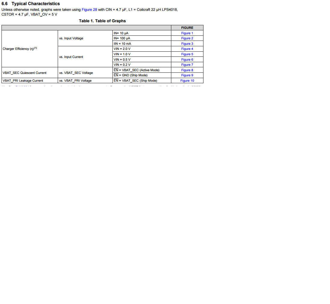
Under Section 6.6 Typical Characteristic, Table 1. It says
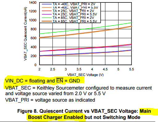
!EN = VBAT_SEC (Active Mode) next to Figure 8
!EN = VBAT_SEC (Ship Mode) next to Figure 10
How can it be in both modes when !EN is tied to VBAT_SEC?
Hi,
Under Section 6.6 Typical Characteristic, Table 1. It says
!EN = VBAT_SEC (Active Mode) next to Figure 8
!EN = VBAT_SEC (Ship Mode) next to Figure 10
How can it be in both modes when !EN is tied to VBAT_SEC?