This thread has been locked.

If you have a related question, please click the "Ask a related question" button in the top right corner. The newly created question will be automatically linked to this question.

LM3478 Boost Converter Output Short Circuit Issue

Other Parts Discussed in Thread: LM3478, LM3488

Hi,

I ma using LM3478 as Boost Converter following are the specs:

VIn: 3 to 5V

Vout: 8V,

Iout: 700mA max

Eff: 85%

Below is the circuit obtained from TI Workbench:

Following were the issues faced:

I wanted to reduce the input & output cap values for same I have kept 33uF input Cap value MLCC & Output Cap value 20uF. RFA=51KOhm. With this configuration I achieve the Line & Load regulation from 3-5V.

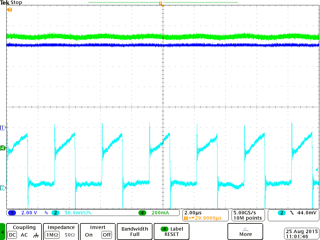
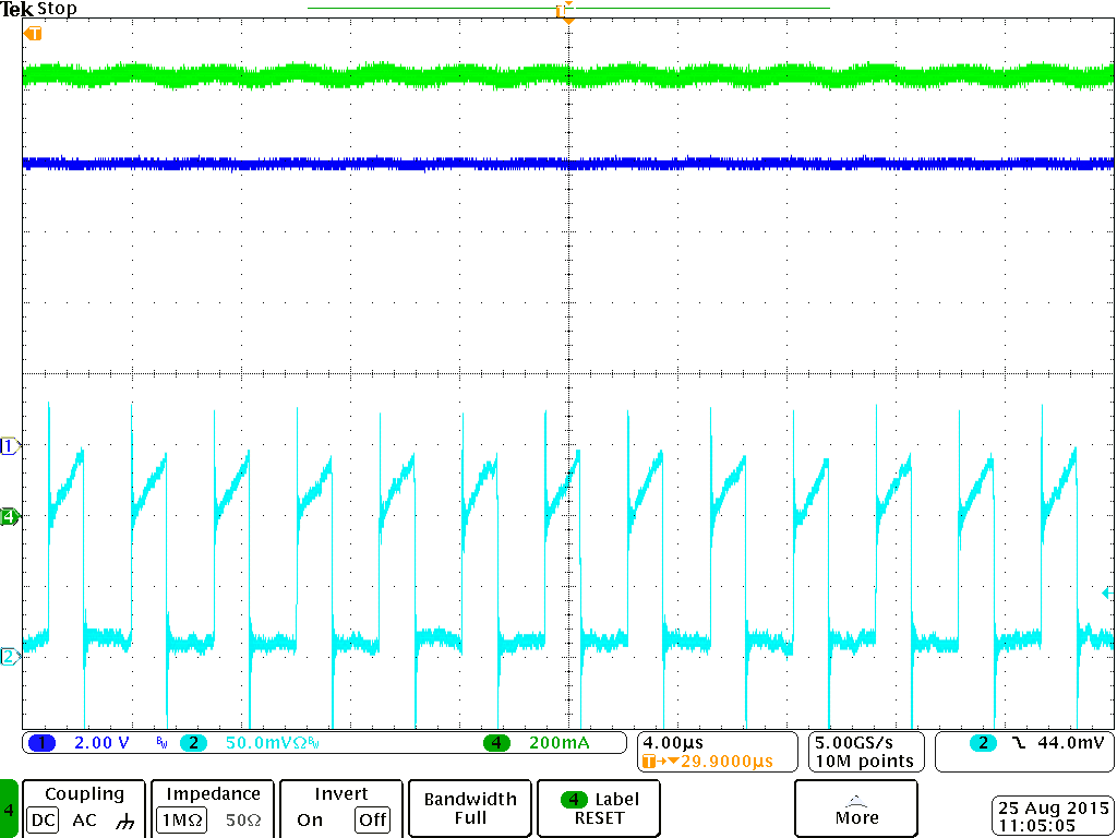
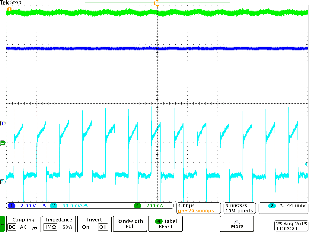
But I am Facing issue with Short Circuit protection & Overload protection. The input supply enters in CC mode and the current is constant at 4.5Amps. Please help me know what might be the issue for same. Overload protection doesn't gets executed till 1Amps though I have designed it for 800mA. I also changed the Rsense to 50mOhm still there is no effect. Please help me for same.

Thanks & Regards,

Shrikant Bhairavkar

  • My Inductor value is 6.8uH, IR=4.2A & ISAT=3.6A, RDC=33mOhm
  • Hi Shrikant,

    Based on your components, following Eq. (19), page 21 of the datasheet,  I estimate that the typical max output current before current limit is reached will be around 1.1A at 3Vin and 2.3A at 5Vin. I assume the switching frequency is around 325kHz.

    That means a peak inductor current of 3.3A at 3Vin and 4A at 5Vin.

    Is the issue occuring at both 3V and 5V? Once the power supply is in CC, the voltage at the input of the LM3478 could drop below the point where the FET is properly driven, depending on the type of FET used. Because there is no maximum duty cycle, the part could run into a case where FET is weakly driven and the peak current is never reached. The part then stays 100% ON which can lead to failure of the FET due to overheating. Is this what you are observing?

    Best Regards,

    Florent Boico

  • Hi Florent,

    I am presently conducting this experiment on TI LM3478 Evaluation board "AN-1204 LM3478/LM3488 Evaluation Board" with Boost Converter Configuration. I have used the same board with my configuration as described. Yes before the current limit peak inductor current is 3.3A at 3Vin and 4A at 5Vin.

    Yes I observe FET getting damaged due to power supply entering CC mode.  This is observed at both 3V & 5V short circuit operation.

    So please let me know whether the inductor saturation current is less or Rsense value should be increased. My INductor 7440650068 value is 6.8uH, 4Amps Rated Current & 3.5Amps Saturation Current.

    Please help me for same,

  • Hi Shrikant,

    The part can only protect itself and the FET during over current events. If the output is shorted, the diode will conduct straight from the input without passing through the FET. Therefore the power supply will collapse regardless of the current. This is the case for boost circuits in general.


    Best Regards,

    Florent


  • Hi Florent,

    Thanks for your reply. Yes I agree t your point since the output is not through FET in case of Boost this will be the case.

    Thanks & Regards,

    Shrikant Bhairavkar

  • Hi Florent,

    With same configuration I am trying to observe over current limit protection. My present value for Rsense is 50mOhm. But I am not able see the overcurrent limit at 1Amps as per design. Please let me know what might be the issue.

    Thanks & Regards,
    Shrikant
  • Hi Shrikant,

    I have built a similar system using a modified eval board. 6.8uH, 8Vout, 50mohm sense resistor.

    I measured the output beginning to drop at 1.25A output current and 0.55A at 3Vin which is close to the estimate I have.

    When the parts is current limiting the part will not shutdown, it will simply limit its peak current each cycle so what you should observe is the output voltage gradually drop as you increase the output current beyond the set current limit.

    The following captures show in green the output current, in dark blue the output voltage and in light blue (cyan) the voltage across the current sense resistor.

    You can see that the voltage stays at 8V as the current is increased (first two screenshots). But above 1.25A (last screenshot) the output voltage begins to drop as the current limit prevents the system from delivering enough current to keep the output voltage at the desired level.

    Best Regards,

    Florent