This thread has been locked.

If you have a related question, please click the "Ask a related question" button in the top right corner. The newly created question will be automatically linked to this question.

the PCAP loss of the LMG5200

Other Parts Discussed in Thread: LMG5200

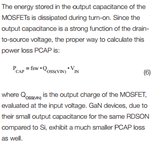
these days i caculated the PCAP loss of the LMG5200,if i use the forum above, then the PCAP loss is:

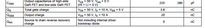
Pcap = 1*20*20*10^-3 = 0.4W          (where Fsw = 1MHz, Vin = 20V, Qoss = 20nC)

Am i right???

if this is true,then when the output Power is 20W,and the efficiency is 95%,so the PCAP loss is the main loss of the total loss

  • There are few things to take into consideration. The first one is that to calculate the loss associated with Qoss, the value at the correct voltage has to be selected. In the example calculation the Qoss valid for 50V is used for a 20V operating voltage.

    At 20V the Qoss will be about half the value that it reaches at 50V.

    Another consideration is that typically, in a hard-switched configuration, you would expect the switching losses to be significant portion of the system losses (especially with increasing frequency and at lower loads).

    We are currently not providing the Qoss over the voltage range as this is a prototype product and subject to changes.

    One last consideration is that the efficiency is also dependent on what conditions the circuit is operated.

    The 95% number used in the example below is reached at 6A of load, converting 48V:12V at 1MHz.

    In the same configuration at output power of 20W the efficiency is ~90%.


  •          so the LMG5200 is a prelimary product,and i see that the Rd of the MOS in it is 18mOhm,and that will be cause the condtion loss going high with the higher output current.

             do Ti  have  other GaN  product plane that will have the better performance than LMG5200?

             In the datasheet,it says that LMG5200 can work at switch frequcency of 5M.but the power loss will be vary high,so i think there is no advantage at that piont.

  • At this point the LMG5200 is the only GaN product that we have available.
    Regarding advantages in applications, considering the efficiency plots above:
    For a high frequency operation , which allows shrinking of passive component for a high density design, the losses of the system using the LMG5200 at 1MHz are reduced by almost half (-45%) than when using comparable 80V Si FET at 800kHz (compare 5% losses vs 9% losses).
    The same 80V Si FET at 250 kHz starts having the similar efficiency as the LMG5200 at 1MHz. The LMG5200 still enjoys a 17% loss reduction.
    If the LMG5200 was run at 250 kHz you would see further improvement.
    At 5 MHz the switching and driving losses will surely increase from the 1MHz level. Depending on design constraints this might or might not be a suitable operating condition.
    The switching losses in a FET at a fixed operating voltage increase linearly with frequency when used in a hard-switched system. Therefore to mitigate these losses, especially at higher frequencies, it is advised to implement quasi-resonant (valley switching) or resonant (Zero-Voltage switching) techniques.
    At which point the only losses that will be present on the FET will be due to conduction losses and (generally smaller in proportion) gate driving losses.
    In summary, the main advantage of the LMG5200 is that at first order the switching losses are greatly reduced in respect with equivalent silicon FET, where switching losses represent a dominant component in the FET losses.
  • Hi,Alberto Doronzo

    i used TI LMG5200EVM,the figure above is test result:

    where Vout  = 4.2V  the x axis stands for frequecy,for example 400 stands for 400kHz,500 stands for 500kHz,etc

          i want to improve the switch frequency to reduce the inductor size,but when i run at 1MHz and the input voltage is 20V,the efficicency is 91%.

         so at that condition,the ratio of inupt and output voltage is 20:4.2.  and it is just equal to 48:12,so from the plot you given,the efficiency should be 95%.but actually not.  Can you tell me reason?

         another question:

         how can i construct vallay switch or ZVS circuit using LMG5200 to improve efficiency?

         did TI has the reference to refer to ?

         and what should i do ?

  • The main difference in the measurements (48:12 vs 20:4.2) is the output power. Since the output voltage is 4.2V at 5A you would get only 21W. At 91.4%, this equates to ~ 1.8W of losses.

    The example where the output is 12V @ 5A (60W) the efficiency is 95%, which means there are 3W of losses.

    To summarize, for this application there are less total system losses when running at a lower power.

     But because  “fixed” losses (capacitive switching losses and gate drive losses), represent a larger share of the total power as the transferred power diminished, the effect is that the results will be lower when computing efficiency, although less heat is generated.

    Because of the level of complexity and detail required to describe the full design for a ZVS circuit, this beyond the scope of this particular forum.

    I would suggest to refer to Zero Voltage Switching Resonant Power Conversion  as a starting point, and use other resources that cover this type of circuits (by instance IEEE has numerous papers on this subject).