This thread has been locked.

If you have a related question, please click the "Ask a related question" button in the top right corner. The newly created question will be automatically linked to this question.

LM5116 with light load

Other Parts Discussed in Thread: LM5116

Hi

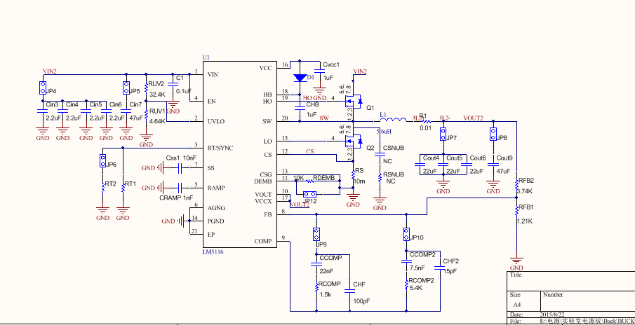
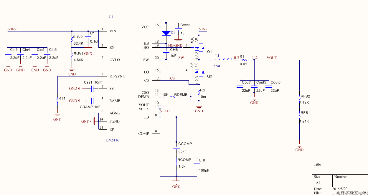
I meet some problem when I use LM5116 for 12V to 5V converter. I add a 10KΩ resistance between DEMB PIN to GND.

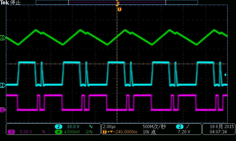
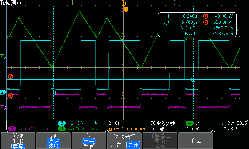
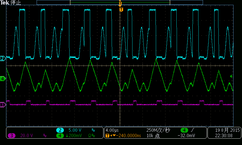
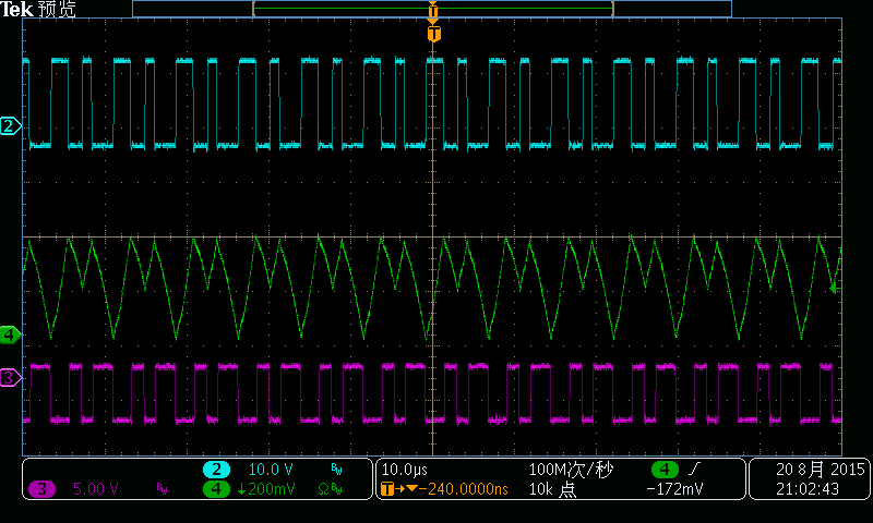
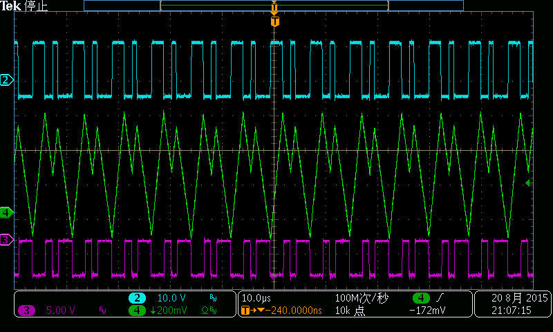
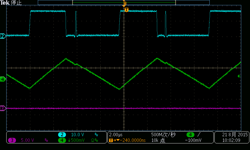
When Iout =0.5A  LM5116 works well . But I gradually reduce the output current when the IC works in FCCM mode the the current is strange.there is a transition in L current's falling.

Can you give me some advice to remove it ? 


Best Regards

 Carry

  • Hi Carry 

    Are you using clock synchronization? 

    What is the purple waveform? 

    Regards,

    EL

  • Hi EL

    I am not using clock synchronization.

    this is the schematic

    the purple waveform is LO PIN and the blue waveform is HO PIN.

    Regards

    Carry

  • Hi EL

    I take the detail about last picture


    In addition

    I try to connect DEMB to GND directly. In principle, LM5116 would  always run in diode emulation. But I find LO pin turn on sometimes.and the HO PIN output is also strange. 

    Channel  2 is HO pin

    Channel 3 is LO PIN

    Channel 4 is Current in L

    I wash there are having some useful information for you

    Regards

    Carry

  • Hi Carry

    Please try;
    Cramp = 680pF ~ 560pF
    Ccomp = 15nF
    Rcomp = 4.87k
    Chf = 150pF

    Regards,
    EL

  • Hi EL

    I use 

    Cramp = 560pF

    Ccomp = 15nF

    Rcomp = 4.8K

    Chf = 150pF

    but the condition is even worse.

    later I use 

    Cramp = 1nF

    Ccomp = 15nF

    Rcomp = 4.8K

    Chf = 150pF

    the flowing is wave

    and I use 

    Cramp = 1.5nF

    Ccomp = 15nF

    Rcomp = 4.8K

    Chf = 150pF

    I ddid not connect Channel 2

    if I use

    Cramp = 2.2nF

    Ccomp = 15nF

    Rcomp = 4.8K

    Chf = 150pF

    the wave didn't  stabe 

    I use Mathcad to calculate the Cramp

    am I right? 

    Ragards 

    Carry

  • Hi Carry 

    My colleague found that you connected COMP to ground. COMP should be connected only to compensation components. 

    Regards,

    EL

  • Hi EL

    I am so sorry about that I made a mistake. the COMP doesn't connect to GND. Because there are a lot of jumper in Schematic ,So I remove it for intuition. And I

    add GND to COMP uncarefully.

    it's the original schematic

    JP4 short ; JP5 open ; JP6 open ; JP7 short ; JP8 open ; JP9 short ; JP10 open  ; JP12 open

    I am so sorry about wasting your valuable time because of my carelessness 

    Regards,

    Carry