This thread has been locked.

If you have a related question, please click the "Ask a related question" button in the top right corner. The newly created question will be automatically linked to this question.

LP2998 as a supercap balancer

Other Parts Discussed in Thread: LP2998

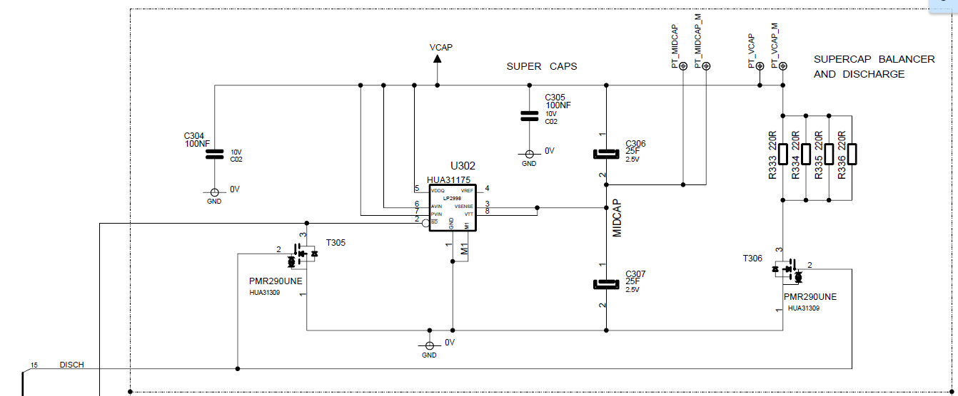
I have been using the LP2998 to balance the midpoint voltage when charging two 25F supercapacitors connected in series.

All three power supply pins are connected to the top capacitor and the output to the midpoint. The charging current is 500-600mA so charging up to 2.6 - 4V takes 30-60s. 

I have seen on one of about a hundred boards that when the voltage reached 1.5V, the LP2998 started to consume all the charging current so the voltage did not rise any higher. Forcing the device into shutdown using the SD-pin allowed the charging to proceed and when activating it again at about 1.6V, it worked fine.

I treid with smaller capacitors but needed to go down to 2x6300uF before it worked as usual.

As I said, I have only seen this on one of about a hundred devices so can I consider this as a faulty device or is there a problem whit this device and very slow voltage ramp-up?


  • Hi Thomas,

    I'd like to understand this issue a bit more. Do you have a schematic you can share? Which pin is reaching the 1.5V when LP2998 starts to consume charging current...Is it the power supply pins (AVIN, PVIN, VDDQ) or the output/midpoint (VTT)? When the voltage reaches 1.5V, which pin is consuming the charging current and which direction, then where does this current go?

    The AVIN pin has a minimum operating voltage of 2.2V and it looks like LP2998 is operating under this voltage for an extended period of time, during which operation may be unpredictable. Can you tie AVIN to 2.2V or higher on a separate line as a debugging exercise?

    Tim

  • Hi Tim

    I have been in contact with your colleague Neal Frager in France. To keep you (and possibly others) in the loop I copy my email response to him here as well.

    *******

    Here is a schematic of the circuitry.

    The super capacitors are C306 and C307. The voltage VCAP is connected to a charger that supplies a maximum current of 500-600mA and it charges up to an adjustable voltage of 2.6 – 4.2V.

    When the signal DISCH is high the LP2998 is shut down and the supercaps are discharged through 55ohms.

    My idea is to split up the DISCH signal into two separate signals. The DISCH signal controls only the right MOSFET (T306) and the new signal controls the left (T305).

    These signals are outputs from a MCU that also measures the VCAP voltage so it can allow the LP2998 to turn on only if VCAP is 2.2V or higher.

    It is bit difficult to connect the AVIN pin to another, higher, voltage.

    ********

    What is your opinion on using the shut down pin as discibed above?

    /Thomas

  • Hi Thomas,
    Schematic is not showing, can you try uploading again?
  • I copied a picture into the text but apparently that didn't work.

    I'll try to attach a PNG-file instead and hope that works.

  • Thanks for sending, I can see it now.

    Since you are splitting the DISCH signal, I would ensure that LP2998 shuts down first with T305, then load activates with T306, so that any amount of surge current does not get accidentally pulled from VTT.

    Also, it might also be good to attach parallel 100k resistors across C306 and C307 to ensure the voltage is kept balanced even when LP2998 is shut down and VTT is floating (ie create a voltage divider with 2x 100k resistors with its midpoint connected to midpoint of caps).

    Have you solved the initial issue from this post? If not, could you give me answers to my initial questions so I can help out?

    Tim

  • Hi Tim

    ***

    Which pin is reaching the 1.5V when LP2998 starts to consume charging current...Is it the power supply pins (AVIN, PVIN, VDDQ) or the output/midpoint (VTT)? When the voltage reaches 1.5V, which pin is consuming the charging current and which direction, then where does this current go?

    ***

    It's when the AVIN, PVIN, VDDQ reaches 1.5V, the LP2998 starts to consume all the charging current (500-600mA). It's like both the output transistors in the LP2998 are conducting. The device also warms up due to the 1W power loss.

    I assume that keeping it in shut-down if the input voltage (VCAP) i below 2.2V will solve it.

    /Thomas

  • Hi Thomas,

    Yes, I suggest keeping it in shut-down if input is below 2.2V. If LP2998 is getting hot, then it is likely running through the PVIN pin and through both FETs as you mention.

    This is probably becuase AVIN is below minimum operating voltage of 2.2V, and the internal comparator has not been completely powered on properly for proper operation and driving of FETs.