This thread has been locked.

If you have a related question, please click the "Ask a related question" button in the top right corner. The newly created question will be automatically linked to this question.

LM5101A keeps burning. Simple circuit 2 mosfet half bridge with LM5101 and an ATMEGA 168 for pwm.

Other Parts Discussed in Thread: LM5101A, LM5101

Hi.. I am new and am trying to put togather a cheap simple motor controller for a series wond DC motor. I currently deisgned a small circuit with an Arduino Uno to provide PWM and high/low side inputs pulses. I have logic to prevent both high and low  inputs from becoming 1 at the same time (using AND and NAND gates). I am using 2 car batteries in series for power. They are connect to an Ada fuit module to generate the 12V connected to the Vdd of the LM5101A.  HS and HB are connected to 10us electrolyte cap (for C boot strap). The HO and LO are connected to the gate of the  high and low side mosfets (IRF 1407 TO220), respectively. The motor spins and we can control the speed using the Arduino Uno (connected to a Pot). However we occasionally burn the LM5101A, but only after we power the entire circuit off then leave it for a whilw then we try to start it again and move the Pot then we see the LM5101A over heat.

We suspect that noise might be causing the low side to turn abruptly (highest possibility).

We also suspect that current is flowing from Motor to LM5101A through the HS (not sure if that is possible).  

If anyone has seen this issue please let me know.

I also have many questions about this chip:  

0. How do I calculate the C boot strap if I want to drive 10 of IRF1407.

1. How can I know if the LM5101A is getting shorted? Meaning can I measure the current at Vdd to see if it is trying to draw more current than it can handle (how can I tell how much current does it draw)?

2. Is it possible for any current from motor or any where else to flow to  HS (connected to drain of low side mofet, source of high side mosfet and motor)?

3. Does any current flow out of HS to the motor?

4. How much heat can an LM5101A take before it gets damaged?

4. Are there any protective components or circuits that I need to add to protect the LM5101A (caps, resistors, etc)?

Appreciate the help in advance.

Thanks

Basem.

  • One more question.. A silly one I know but just want to confirm. All the grounds have to be the same? Meaning the ATmega ground, the motor ground and the MOSFET source for the low side are connected to the -ve terminal of the battery.. Right ?
  • Basem,

    I can only guess about this since you don't provide a schematic. (If you could provide one it would make things a lot easier.) Anyway, if you have two 12 V batteries in series, that means you have a 24V source, right? So your motor is a 12V DC motor. Depending on how hard the bottom MOSFET is turned on, you could have as much 2 or 3 V dropping across the LM5101A. With 3 V across the device and 3 A through it, the part is dissipating 9W.  Could be more, I don't know.  The SO8 power pack has a 40 deg C/W thermal resistance. So with 9 W times 40 deg C/W the case temp is 120 deg C. The max operating temp is 125 c. I bet it is getting pretty hot. 

    Send the schematic. That way we don't have to guess. 

    Good luck,

    Chuck

  • Hi Chuck.. Thanks for taking the time to respond. Really appreciate it. I will try to send the schematic as soon as I can.. Trying to figure out how to upload it.
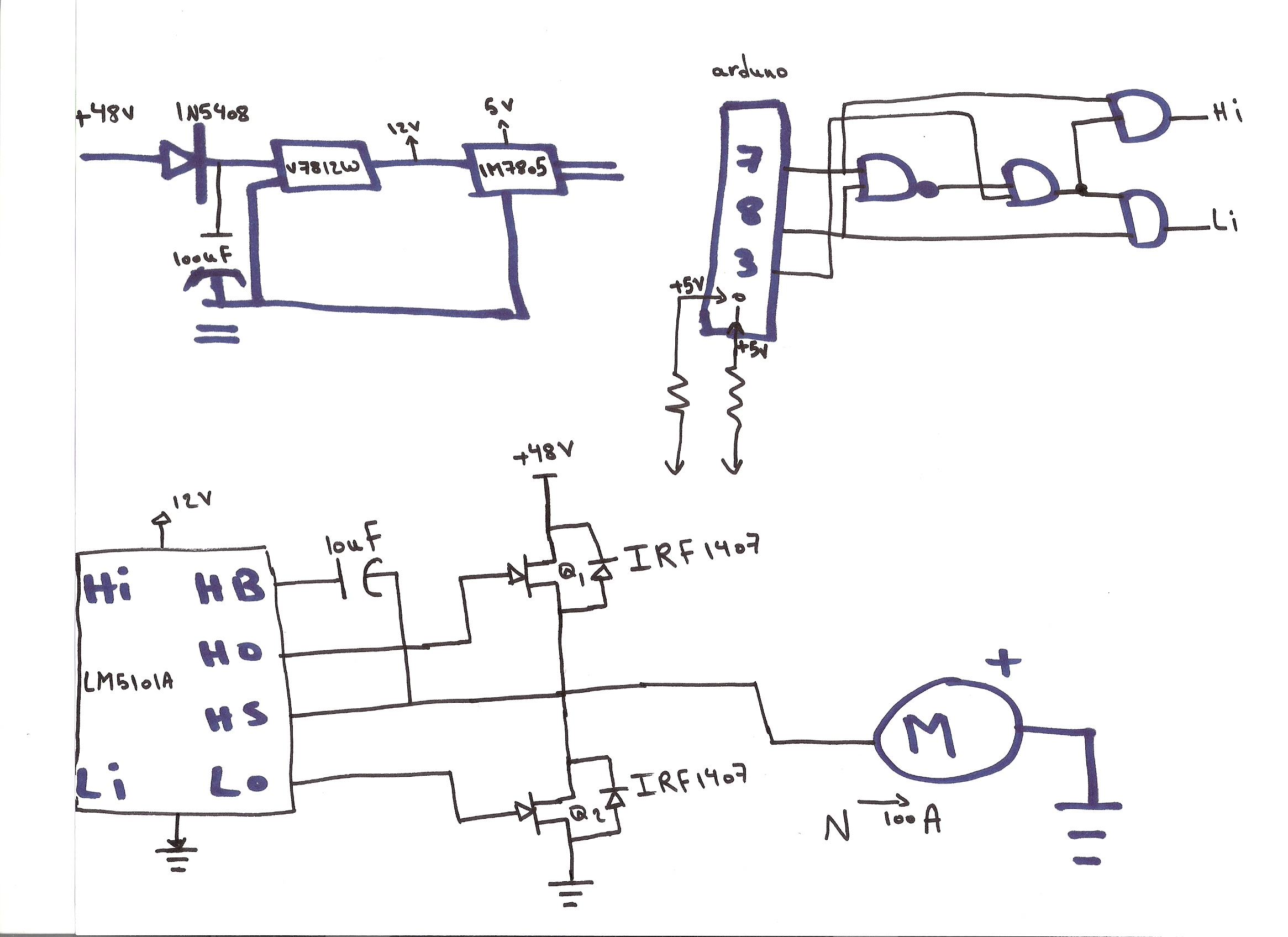
  • Hi Chuck.. Apologize for the delay but tried to do it with a computer software, but failed. I drew it by hand, as I do not want to waste anymore time trying to figure out the various free softwates. (I tried multisim but it did not have all the parts that I need, With windows 8 something is wrong with visio, word/power point took way too long). Here is the schematic below:

    The and gates, variable resistor and arduino Uno are using the 5 volts from the  LM7805 chip. The LM5101A, Vdd is coming from the Ada Fruit module V7812W. I am using 4 lead acid car batteries to generate the 48V and 100A. The motor is a fork lift motor (does not have any specs), but it can handle the 48V and 100A (not sure how much current it is drawing though).

    Thanks

  • Basem,

    I looked over you schematic and I have a few suggestions. 

    I see in your schematic that you are using a 10 uF bootstrap capacitor. 10 uF is a very large value for this application. They are usually in the 10 to 47 nF range. The power dissipated in the high side drive is CV^2F. The larger this bootstrap capacitor value is, the more power is dissipated in the chip. You need to know what frequency and what power level you need to drive the motor in order to properly size this component. It determines how much power the LM5101A dissipates.  

    Whenever I design a circuit, I start with the load requirements. I suggest you test the motor to determine its motor resistance and motor inductance using the instruction in app. note at the link below:

    http://support.ctc-control.com/customer/elearning/younkin/motorParameters.pdf

    Then once you know the inductance and motor resistance you can determine the necessary switching frequency by using the formula Vripple = Linductor*di/dt. For a 48 V, 100 A DC rated motor you will need a hefty power bridge. Make sure your MOSFETs can handle this large current and conduction losses as well as switching losses. I would think you would need a lot more than 2 batteries in series to maintain maximum power from this motor.

    From there you need to calculate the value of your bootstrap capacitor.

    https://www.fairchildsemi.com/application-notes/AN/AN-6076.pdf

    One reason I see that may be causing the over-heating problems with the LM5101A driver is explained in the enclosed app. note:

    http://www.ti.com/lit/an/snva083a/snva083a.pdf

    You may have just left these parts out on your schematic -but in case you didn't -you need 1uF or higher input and output capacitors for the LM7805 and LM7812 as well as a couple of small 10 nF capacitors for the noise. The +48V buss will need large value 10uF to 100uF capacitors close to the drain of the topside MOSFET.

    Good luck on your design,

    Chuck

  • Hi Chuck.. Appreciate the reply and the valuable information there. I am still reading through it and trying to digest  it.

    The frequency I am using is 4KHz. For the final test (~500Kg load) I am using an array of MOSFETs, about 7 to 10 0n high side and 3-5 on low side. That is why I used a large 10uF cap. I am not sure how to calculate the bootstrap but I found a website where you enter a few params from the IRF 1407 data sheet and it tells you the bootstrap value. After playing around the value it gave was ~3-5 uF so I used 10uF.

    As for the caps before and after the supply, I actually did not use, do you think that is what is causing the issue (LM5101A burning). The part that puzzles me is that it usually burns at the beginning of a trial, and most of the times third trial. It usually sits for about 20 - 30 min before each trial. It seems that the LM5101A is damaged close to the end of the trial.

    What bootstrap cap value do I need if I want to drive about 20 of the IRF 1407?

    As for the large cap close to the drain of the MOSFET, does the other terminal connect to the -ve of the battery or the HS line ?

    When I use a small test motor (30V and 4A max current) the LM5101A does not burn, even if I test it 20 times, using the same cap value (10uF)  This setup uses a clean power supply (no car batteries). Do you still think overheating is still the issue ? If the cap value is the problem should it not over heat even with the small motor?

    If you can suggest the proper bootstrap cap values, I can replace the cap and test the external diode solution, can use any diode or must it be a special diode ? A part number would be awesome.

    Appreciate your help in advance.

    Thanks

    Basem.

  • Hi Basem,

    "The frequency I am using is 4KHz. For the final test (~500Kg load) I am using an array of MOSFETs, about 7 to 10 0n high side and 3-5 on low side. That is why I used a large 10uF cap. I am not sure how to calculate the bootstrap but I found a website where you enter a few params from the IRF 1407 data sheet and it tells you the bootstrap value. After playing around the value it gave was ~3-5 uF so I used 10uF."

    Can you direct me to this website? What MOSFET parameters did you use to get the bootstrap value of 3 to 5 uF?  3 to 5 uF may be the required total bootstrap capacitance value needed to drive all your MOSFETs. The key here is to determine how much power you need to drive the MOSFETS and then check the LM5101 to see if can dissipate that much power. The LM5101 has a thermal resistance. Multiply the power dissipated by the thermal resistance and add this value to the ambient temperature. If the total temperature is above the maximum operating Tj for the LM5101, the device will fail.  I would use a separate driver for each MOSFET. Also, I would choose a MOSFET with a low Qgs and Qgt so that I didn't dissipate a lot of power in the gate drive circuit. 

    What bootstrap cap value do I need if I want to drive about 20 of the IRF 1407?

    I would use the application note at the link I provided to calculate the value and use a separate gate drive for each power bridge. I would use no more than two MOSFETs in parallel. You are trying to parallel too many MOSFETS. That is why your gate driver is burning up. Driving 20 MOSFETS in parallel requires a lot of gate drive power. You need to use a larger, higher current, lower RDSon MOSFET that is optimized for a switching application -low gate charge. 

    "As for the caps before and after the supply, I actually did not use, do you think that is what is causing the issue (LM5101A burning). The part that puzzles me is that it usually burns at the beginning of a trial, and most of the times third trial. It usually sits for about 20 - 30 min before each trial. It seems that theLM5101A is damaged close to the end of the trial."

    Yes, I think that could be one of the reasons you are getting negative test results. When I design a circuit, I break down the system into small subcircuits and test each one to make sure they each work. I also refer to the data sheet for the part, like the LM7812, and look for reference designs. If they have the circuit I need I copy it. Without any capacitors on the input or the output of the LM7812, I would guess the voltage input to the LM5101 is either oscillating or dipping each time the gate driver outputs a pulse voltage to the MOSFET gate. Check this with an oscilloscope. Each time the gate driver pulse a high current, it needs the charge stored in the output capacitor of the 7812 and the capacitor connected to the LM5101 vdd pin to keep the bias voltage from drooping. 

    "As for the large cap close to the drain of the MOSFET, does the other terminal connect to the -ve of the battery or the HS line ?"

    For the large capacitor on the bus voltage, I would use several in parallel to reduce the capacitor esr and ripple. The capacitors are connected from the high-side MOSFET drain to ground or -ve. 

  • Hi Chuck..

    Here is the website I used to estimate the bootstrap cap.

    "www.silabs.com/.../bootstrap-calculator.aspx"

    It allows you to calculate for a max of 4 MOSFETs. So I started with 1, then 2, then 3, then 4 to see the pattern and I extrapolated to the number of MOSFETs.  I am not sure why there is no easy way to do this, It seems to me tha the LM5101A should be able to drive a large number of IRF 1407s, again not an expert,

    Is there no one trying to do what I am doing ?

    What is bugging me till now is the following.

    I am working in steps, so first I used 2 MOSFETs (IRF 1407 for high side and low side), with a small motor 30V 4A and a power supply that can supply up to 33V and 5A, same circuit, no issues with the LM5101A. Then I switched to the car batteries but only 3 with the same motor, no issues. Then switch to 4 with the same motor no issues. Once I use the large motor, I start to see the LM5101A burn up. In all the cases I am using 10uF and 2 MOSFETs, since the motor is only drawing <20A with no load. The 2 things I can think of that are causing the burn up due to the large motor, is that current is flowing from the motor to the LM5101A some how? Or the heat from the large motor is causing the LM5101 (connection from HS) to heat up and burn. I am not sure though.

    I never paid attention whilte testing but itseems to me the problem might be due to the car batteries. I probably should do an experiment with the small motor using car batteries, if the LM5101A burns up. Then we know the problem. But the small motor draws mill amps so might not be enough to expose a real issue. So it might be better to test using the large motor with 4 car batteries and monitor the 12 V line and the HS line.

    Is it possible for any current to flow from the motor to the LM5101A through the HS line ?

    You suggested using caps close to the Drain and also fo rthe 12V and 5V.

    For the 12V I am using a module from Ada fruit that shold have all the caps and inductors. For the 5V I will add some large and small value caps. I will also add a cap betweent the drain of the high side and -ve terminal of the battery. I will also add a diode connected to the bootstrap cap to offload the LM5101A, and see if things improve.

    Appreciate your help in advance.

    Thanks

    Basem.

  • "Is there no one trying to do what I am doing ?"

    Yes there are many people doing what you are trying to do, see the link below:

    http://www.instructables.com/id/Homemade-100-HP-Motor-Controller-for-an-Electric-C/

    -Chuck

  • Hi Chuck...

    I read through the application note you provided the link for.. It seems my circuit lacks lots of protection from undershoot. I have to add those as well. Thanks for your help, the docs you provided were really useful.

    After reading all this. I have one question is it better to use a P-channel MOSFET in stead for the N-channel MOSFET for the high side ? I will start my research on this but if you have any info or experience that you can share, that would be very helpful.. Really appreciate your help.

    Thanks

    Basem.

  • Basem,

     "I have one question is it better to use a P-channel MOSFET in stead for the N-channel MOSFET for the high side ?"

    Whether to use a P-channel or N-channel for the high side switch is good question. Some designers go with the P-channel because the high side drive is less complicated, while others use the N-Channel MOSFET to achieve higher efficiency. The N-channel MOSFET has approximately half the conduction losses of a P-Channel. 

    -Chuck