This thread has been locked.

If you have a related question, please click the "Ask a related question" button in the top right corner. The newly created question will be automatically linked to this question.

LM2700 - Reduced Output current issue

Other Parts Discussed in Thread: LM2700

LM2700 performance analysis.xlsxHi,

We have been testing the LM2700EVM for our product feasibility analysis.

The desired input voltage range is 2.2V - 4.6V. The LM2700 is connected to an LED Load with a Forward voltage of 9V and forward current of 210mA (max).

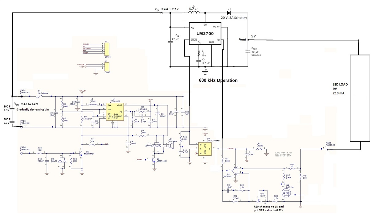
The test circuit we had used for this testing is shown in the attachment. One thing we would like to highlight is the kind of Feedback circuit we had used. The LED load will be connected to an non-inverting Op-Amp circuit (with a gain factor around 21), the output of which will be the actual feedback voltage for the LM2700.

- As per the test data, we had tabulated, you could see the output current of the LM2700 falling down when the input voltage falls below 2.4V or 2.35V. It was also noted that the corresponding input current is getting reduced at such a operating input voltage condition.

- Also the LM270 IC was seen to gradually heat up when we gradually descend the input voltage beyond 2.5V.

Could someone throw more light on the actual rationale behind this behavior of the LM2700?

Thanks,
Santhosh S

  • Hello Santhosh,

    I am not the expert on this part, but I will try to add some comments.

    Looking at the schematic, it looks like the FB node is connected to GND. This must be a typo...can you upload your real schematic? Are the input voltage measurements at the VIN pin of the IC? If not, what is the actual voltage at the IC VIN pin?

    Do you have a board layout we can look at?

    Cheers,

    Denislav

  • hi Denislav,

    I am working with Santhosh on this and replying on his behalf.

    1. FB pin/node is not connected to GND. Its is connected to the output pin of the op amp U4.
    2. Sorry we cannot provide schematic and layout right now. But we shall try if we can. If feasible, it shall be done by EOD.
    3. Yes, the input voltage measurements are made at the Vin pin of the LM2700 IC. The voltage supply is from a charged capacitor of 300F(working as battery). The voltage starts from 4.6V and as the device is operated, it keeps falling gradually. LM2700 works till 2.2V. So the Vin can be anywhere between 4.6 to 2.2V.

    Regards,
    Awtar
  • Awtar,

    We are currently investigating your scenario in the lab. We have confirmed a few things including input current limit and calculation seems to be fine. However, it looks like it's a feedback issue. Analyzing the data you sent, the part doesn't have stable switching at any input voltage. There were a few things I need clarification on. 

    1. Why are you using an OP-amp in constant current feedback instead of a simple sense resistor? Is there any particular reason for the gain ?

    2. Have you tried replacing the op-amp with a shunt?

    3. Can you provide a clear schematic for the diagram?

    Best

  • Hi Kaisar,

    Many thanks for your comment.

    Reply for 1. We need consistent dimming in LED light output at regularly intervals. It is a requirement. So we are using Op-amp for feedback purpose.

    Reply for 2.

    a) We had tested LM2700 EVM having resistive feedback and resistive load of 36 ohm.. This test was done WITHOUT integrating the EVM with main board. LED load was NOT used. The results were satisfactory. Sharing the same.5148.e2e.xlsx

    b) We had NOT tested the test setup of LM2700 EVM + our main board + resistive feedback + LED load. It is because, the op-amp feedback is a must for our circuit requirement to get regular dimming of LED light at fixed intervals. So even if the resistive feedback works fine, it is useless for us.

    Reply for 3. We have the schematic in image format only(shared already inside excel). Still attaching here with more clarity. Please suggest if you are looking for something else too.

    Thanks

    Warm Regards,

    Awtar