Hi,
I'm using the TPS62737, Ultra-Low Power Buck Converter, to convert a lithuim coin cell rechargeable battery to an 2.5V to feed the circuits on my board. Here's the datasheet : www.ti.com/.../slvsbo4c.pdf
the input voltage is variable, starting from 4.2V when the coin cell is fully charged to 2.75V when the battery is discharged. here's the battery datasheet : www.ti.com/.../slvsbo4c.pdf
the desired output voltage is 2.5v to feed the microcontrollers and other circuit and the VIN_OK threshold is about 3.35v. for that i use the 3 resistors methode using these values R1 = 4.7M, R2 = 1.6M, R3 = 6.7M. using
So i have 2 question :
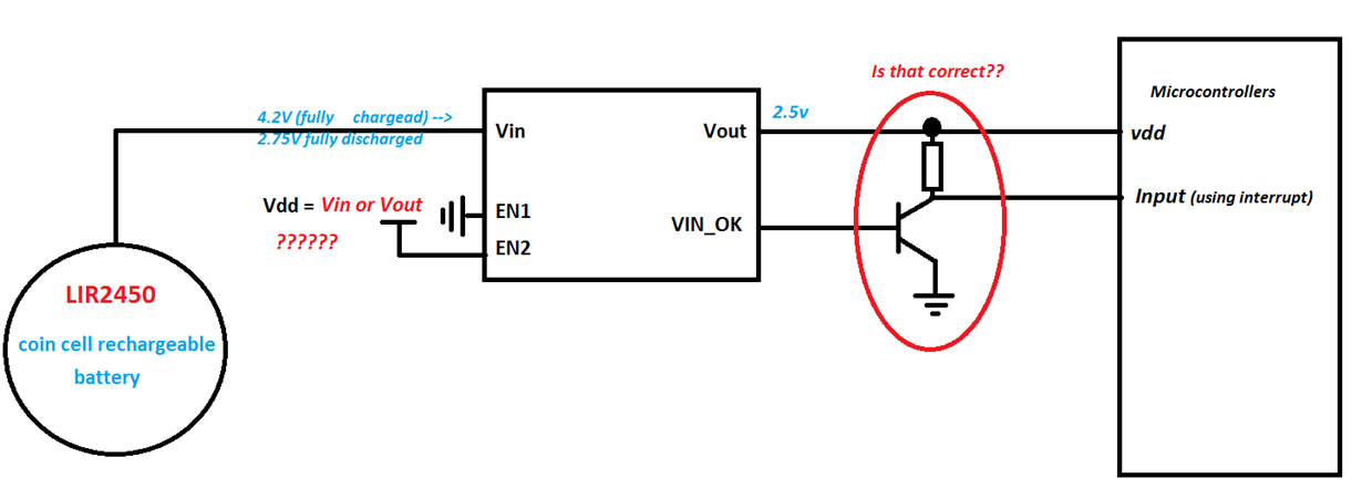
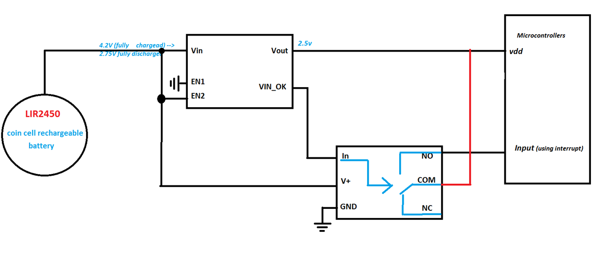
1/ to put the TPS62737 into the normal mode ,meaning Buck mode ON and VIN_OK enabled, i have to put the EN1 pin to the Gnd and the EN2 to the Vdd. but i don't know which vdd should i use. the VDD of the VIN (battery voltage) or the output voltage 2.5V ??
2/ the VIN_OK output signal which indicate to the microcontroller that the input voltage is OK. i don't know if i have to use an external Pull-Up resitor and connect it to the Vout, or the VIN_OK has an internal Pull-Up resistor and in this case i have to use an external transistor to match the voltage level? if that correct which transistor should i use to minimize the power consumption ?
here's a picture of the circuit :
Thanks for the help,


